
Integrated lost motion rocker brake with automatic reset

a technology of automatic reset and lost motion, which is applied in the direction of valve details, valve arrangement, valve drive, etc., can solve the problems of braking and egr performance problems, difficulty in adjusting timings and/or amounts of engine valve lift, and excess exhaust gas flowing back into the cylinder and into the intake manifold

Active Publication Date: 2014-03-27
JACOBS VEHICLE SYST
View PDF0 Cites 55 Cited by
  • Summary
  • Abstract
  • Description
  • Claims
  • Application Information

AI Technical Summary

Benefits of technology

The patent text describes an innovative system for actuating an engine valve using a rocker arm and a hydraulic actuator piston. The system includes a sliding pin and a reset piston assembly that work together to mechanically lock the actuator piston in a specific position. The actuator piston has a contact surface that acts on the valve bridge to actuate the engine valve. The system also includes a hydraulic passage and a control valve to maintain the actuator piston in the extended position for multiple engine cycles. The technical effect of this system is to provide a reliable and efficient way to actuate engine valves.

Problems solved by technology

The use of fixed profile cams, however, can make it difficult to adjust the timings and / or amounts of engine valve lift to optimize them for various engine operating conditions.
This added valve lift may create an increased overlap between the main exhaust event and the main intake event, and cause excess exhaust gases to flow back into the cylinder and into the intake manifold.
This result may lead to braking and EGR performance issues, such as higher injector tip temperature and lower engine retarding power.
In addition, the added valve lift may cause reliability issues, including increased potential of valve-to-piston contact.
Additional systems that may be added to existing engines are often cost-prohibitive and may have additional space requirements due to their bulky size.
Pre-existing engine brake systems may avoid high cost or additional packaging, but the size of these systems and the number of additional components may often result in lower reliability and difficulties with size.
It is thus often desirable to provide an integral engine braking system that may be low cost, provide high performance and reliability, and yet not provide space or packaging challenges.

Method used


Image

  • Integrated lost motion rocker brake with automatic reset
  • Integrated lost motion rocker brake with automatic reset
  • Integrated lost motion rocker brake with automatic reset

Examples


first embodiment

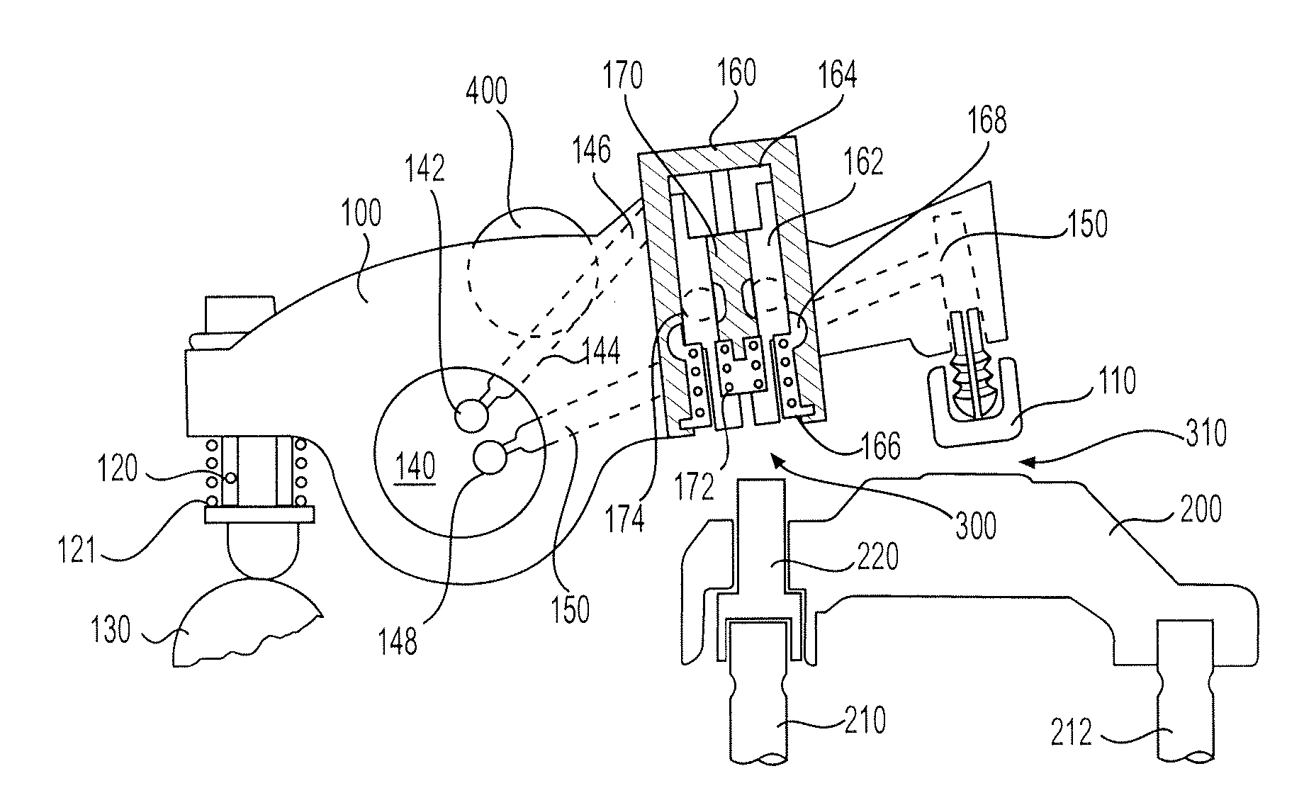
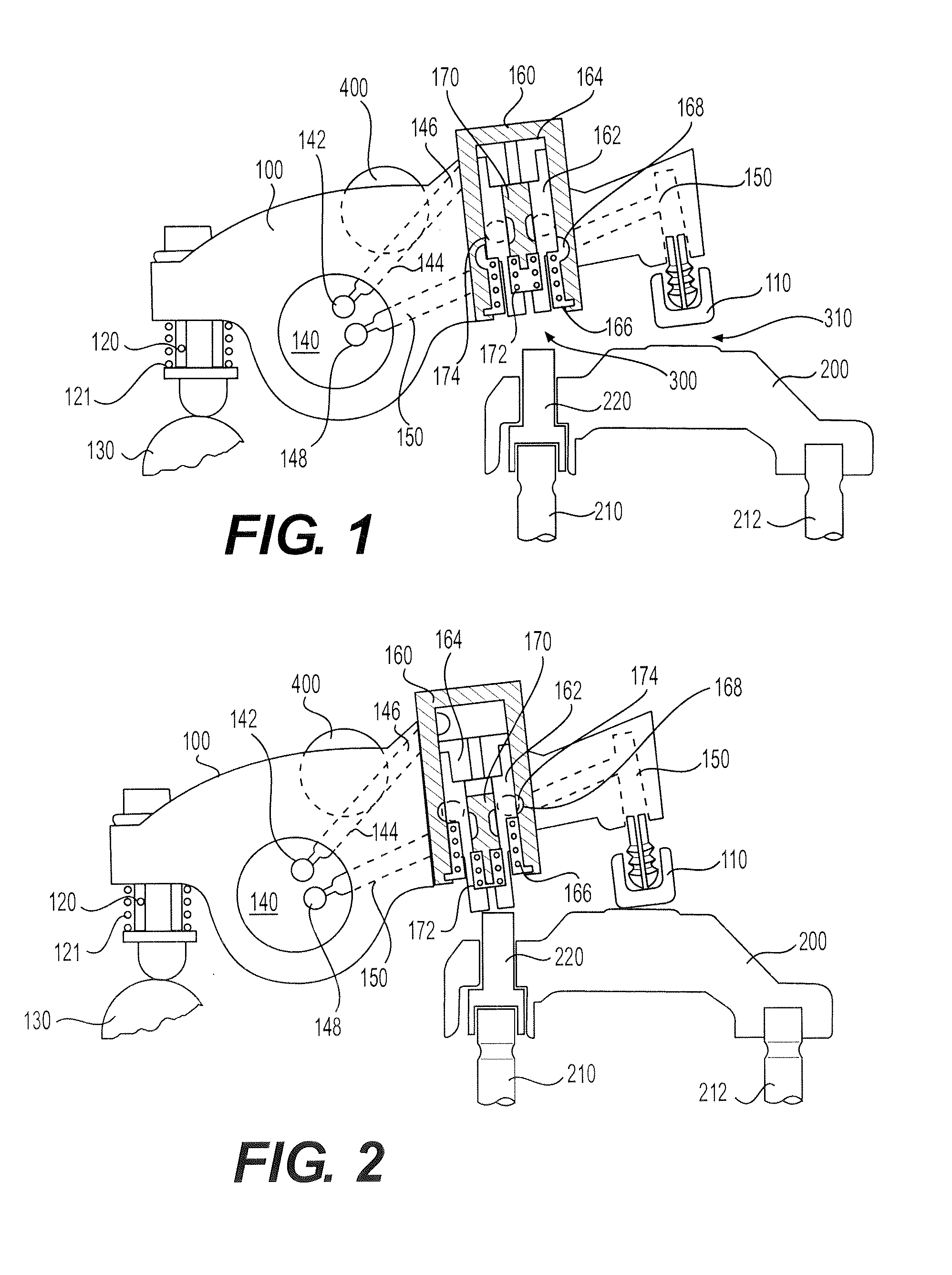
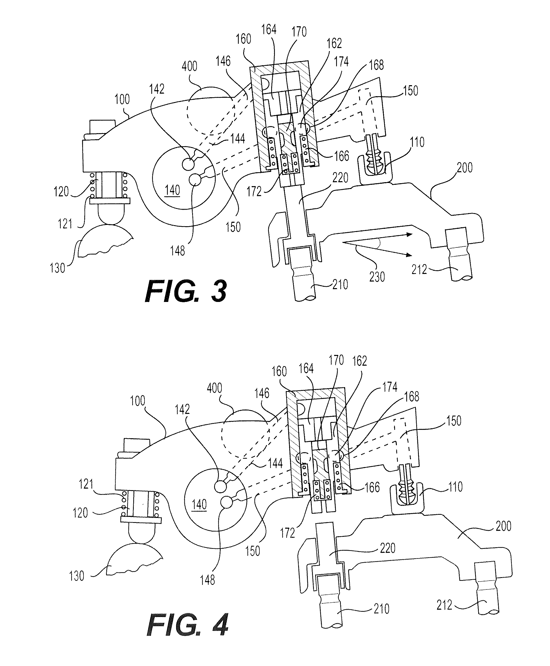
[0049]With reference to FIGS. 1-4 and 13, schematic views in partial cross-section are shown of an exhaust rocker arm 100 and an associated exhaust valve bridge 200 in accordance with the present invention. The exhaust valve bridge 200 is preferably a “floating” bridge, meaning that there is no central guide below the valve bridge which permits the floating bridge to tilt relative to the engine valve stems 210 and 212 that it bridges (see tilt angle 230 in FIGS. 3 and 7). The valve bridge 200 may include a sliding pin 220, or contact surface in an alternative embodiment, which is received in an opening provided in the valve bridge above the inboard exhaust valve 210. The sliding pin may be capable of translating downward relative to the valve bridge 200, instead of or in addition to the tilting of the valve bridge, to permit actuation of the inboard exhaust valve 210 without actuation of the outboard exhaust valve 212. It is appreciated that a contact surface provided integrally wit...

fifth embodiment

[0074]With reference to FIG. 22, in an alternative fifth embodiment of the invention shown in FIGS. 14-17 in which like reference characters refer to like elements, the reset piston 112 may include a swivel foot 111 which acts on a contact surface adjacent to the center portion of the valve bridge 200 over the outboard exhaust valve 212. In this embodiment, the rocker arm contact surface (i.e., swivel foot 110) which is adapted to act on the center portion of the valve bridge is provided between the reset piston 112 and the actuator piston 196. The embodiment shown in FIG. 22 operates like that shown in FIGS. 14-17 in all other respects.

[0075]With reference to FIGS. 18-21, schematic views in partial cross-section are shown of an exhaust rocker arm 100 and an associated exhaust valve bridge 200 in accordance with a fourth embodiment of the present invention in which like reference characters refer to like elements to those illustrated in connection with the first, second and third em...

sixth embodiment

[0084]With reference to FIG. 23, in an alternative sixth embodiment of the invention shown in FIGS. 18-21, in which like reference characters refer to like elements, it is shown that the reset piston second annular recess 250 may selectively provide hydraulic fluid communication between the connecting passage 245 and an ambient via opening 248. In this manner, opening 248 may provide an alternative route for the venting hydraulic fluid from the connecting passage 245 to reset the locking piston (not shown) to that shown in FIGS. 18-21. The system shown in FIG. 23 may operate in the same manner as that shown in FIGS. 18-21 in all other respects.


PUM


Abstract

Systems and methods for actuating engine valves are disclosed. The systems may include a rocker arm having an adjustable length push tube mounted to a first end and multiple contact surfaces for an engine valve bridge at a second end. An actuator piston assembly may be provided in the rocker arm between the first and second rocker arm ends. The actuator piston assembly is adapted to extend from the rocker arm under the influence of hydraulic pressure and actuate an inboard engine valve through the engine valve bridge when an actuator piston is locked into an extended position.

Description

CROSS-REFERENCE TO RELATED APPLICATIONS[0001]The present application relates to, and claims the priority of, U.S. Provisional Patent Application Ser. No. 61 / 704,742, filed Sep. 24, 2012, which is entitled “Integrated Lost Motion Rocker Brake With Automatic Reset.”FIELD OF THE INVENTION[0002]The present invention relates to systems and methods for actuating valves in internal combustion engines.BACKGROUND OF THE INVENTION[0003]Internal combustion engines typically use either a mechanical, electrical, or hydro-mechanical valve actuation system to actuate the engine valves. These systems may include a combination of camshafts, rocker arms and push rods that are driven by the engine's crankshaft rotation. When a camshaft is used to actuate the engine valves, the timing of the valve actuation may be fixed by the size and location of the lobes on the camshaft.[0004]For each 360 degree rotation of the camshaft, the engine completes a full cycle made up of four strokes (i.e., expansion, exh...

Claims


Application Information

Patent Timeline
IPC IPC(8): F01L1/18
CPCF01L1/18F01L1/08F01L1/181F01L1/267F01L13/06
Inventor ROBERTS, GABRIEL SCOTTBALTRUCKI, JUSTIN DAMIENNELSON, SCOTT
Owner JACOBS VEHICLE SYST
Learn More