Heat exchanger

a technology of heat exchanger and heat exchanger plate, which is applied in the direction of tubular elements, lighting and heating apparatus, stationary conduit assemblies, etc., can solve the problems of significant decrease in static pressure in the inlet region, and adversely affecting the efficiency of the evaporator

Inactive Publication Date: 2014-03-27
MAHLE INT GMBH
View PDF21 Cites 3 Cited by
  • Summary
  • Abstract
  • Description
  • Claims
  • Application Information

AI Technical Summary

Problems solved by technology

Said warm zones can adversely affect the efficiency of the evaporator.
A disadvantage of this is that, in particular in the case of large mass flows or high vapor flow speeds, a considerable decrease in static pressure takes place in the inlet region owing to the Bernoulli effect.
This likewise leads to the formation of warm zones which adversely affect the efficiency of the evaporator.
A disadvantage here is that, in particular in the case of high mass flow rates, it must be assumed that the individual openings are impinged on with a different vapor fraction of the refrigerant, which leads to a severely uneven distribution in the collecting tank.
This rather intensifies the problems such as the generation of warm zones.
It i

Method used


Image

  • Heat exchanger
  • Heat exchanger

Examples


Embodiment Construction

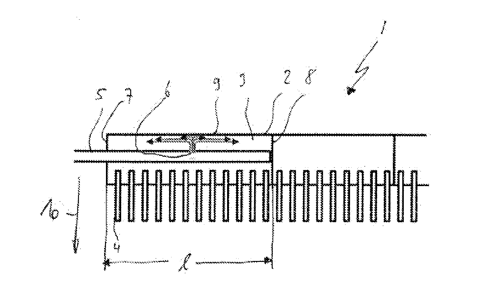
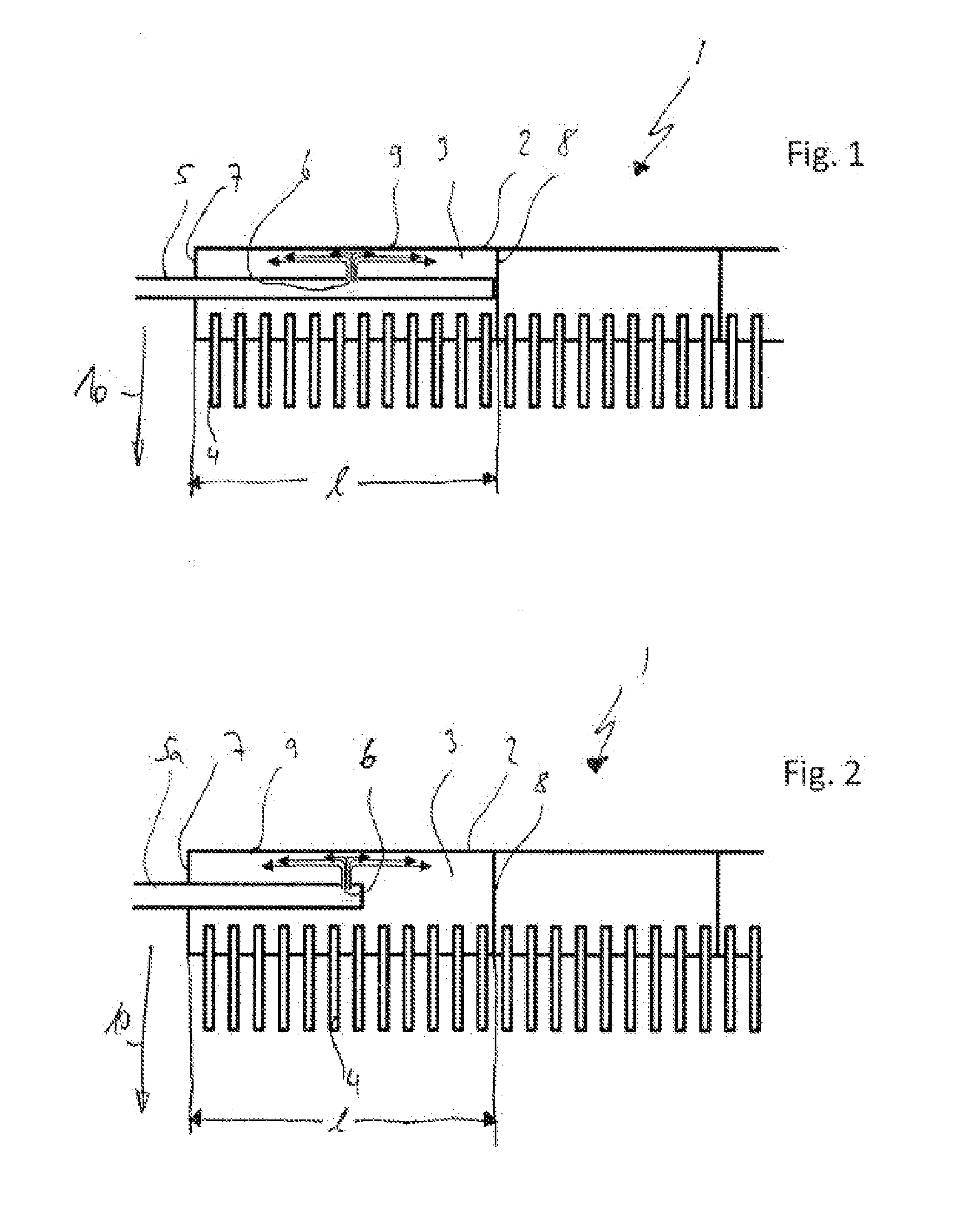
[0045]FIG. 1 shows a section through a heat exchanger 1. In detail, FIG. 1 illustrates a section through a collecting tank 2. The heat exchanger 1 has in each case one collecting tank 2, 2a at two opposite sides. The two collecting tanks 2, 2a are connected to one another via the flat tubes 4. A refrigerant can flow between the collecting tanks 2, 2a via the flat tubes 4.

[0046]FIG. 1 and FIG. 2 illustrate in each case only one of the two collecting tanks 2, 2a. The collecting tank 2 shown in each case has the inflow region of the heat exchanger 1.

[0047]The collecting tank 2 of FIG. 1 is divided into multiple chambers by partitions 8. A refrigerant flowing into the collecting tank 2 can propagate in each case only along one of said chambers before it flows over into the respective second collecting tank 2a through the flat tubes 4. The refrigerant is distributed further in said second collecting tank 2a and flows via further flat tubes 4 into the next chamber of the collecting tank 2...


PUM


Abstract

Heat exchanger having a block of flat tubes arranged parallel to one another and having fins arranged between the flat tubes, wherein the flat tubes form flow ducts through which a refrigerant can flow, and a coolant can flow around the flat tubes, wherein the flat tubes are in fluid communication, at end regions, with collecting tanks, wherein the refrigerant can be made to flow into an inflow region of a collecting tank in fluid communication with at least one of the flow ducts, wherein the inflow region has a line, which extends through the inflow region, for inflow of the refrigerant, wherein a refrigerant passage is provided from the line to the collecting tank inflow region, said refrigerant passage arranged in the central region of the collecting take inflow region, wherein the central region is in relation to a direction oriented perpendicularly to a plane of the flat tubes.

Description

TECHNICAL FIELD[0001]The invention relates to a heat exchanger having a block of flat tubes arranged parallel to one another and having fins arranged between the flat tubes, wherein the flat tubes form flow ducts through which a refrigerant can flow, and a coolant can flow around the flat tubes, wherein the flat tubes are in fluid communication, at their end regions, with collecting tanks, wherein the refrigerant can be made to flow into an inflow region of a collecting tank which is in fluid communication with at least one of the flow ducts.PRIOR ART[0002]Evaporators in air-conditioning systems of motor vehicles are often traversed by a flow of refrigerant. Here, the refrigerant, which is present in a two-phase state, is changed completely into a gaseous phase in the evaporator.[0003]At the time at which it is introduced into the evaporator, the refrigerant has both a liquid and also a gaseous phase.[0004]In the use of flat-tube evaporators, it is advantageous for the two phases to...

Claims


Application Information

Patent Timeline
IPC IPC(8): F28F1/12
CPCF28F1/12F28F9/0209F28F9/027F28D1/05375
Inventor FEUERECKER, GUNTHER
Owner MAHLE INT GMBH
Why Eureka
Try Eureka