Windowless h-bridge buck-boost switching converter

a buck-boost and converter technology, applied in the field of buck-boost switching converters, can solve the problems of buck-boost mode typically not being sustained, buck-boost mode typically not being able to continue working, and poor efficiency when operating in buck-boost mode. , to achieve the effect of reducing the number of mode transitions, and improving efficiency

Active Publication Date: 2014-03-27
ANALOG DEVICES INT UNLTD
View PDF7 Cites 56 Cited by
  • Summary
  • Abstract
  • Description
  • Claims
  • Application Information

AI Technical Summary

Benefits of technology

[0014]The present arrangement operates to shift the ‘ramp’ signal up by Vhys+Vslp(p−p) when transitioning from buck to boost mode, and to shift ‘ramp’ back down by Vhys+Vslp(p−p) when transitioning from boost to buck mode. This enables the converter to operate with only two modes—buck and boost—with no need for an intermediate buck-boost region. As such, the number of mode transitions is reduced, and there are never more than two switching elements being switched—thereby providing improved efficiency. Output voltage discontinuities are also minimized with only two operating modes.

Problems solved by technology

However, if the battery voltage is just slightly above 3.3 v, the converter is typically unable to continue working in buck mode, and must switch to buck-boost mode operation.
Similarly, boost mode typically cannot be sustained when the battery voltage is just slightly below 3.3 v, requiring the converter to switch to buck-boost mode operation.
There is a drawback to this method of operation, however: due to the need to be switching all four switching elements, efficiency is poor when operating in buck-boost mode.

Method used


Image

  • Windowless h-bridge buck-boost switching converter
  • Windowless h-bridge buck-boost switching converter
  • Windowless h-bridge buck-boost switching converter

Examples


Embodiment Construction

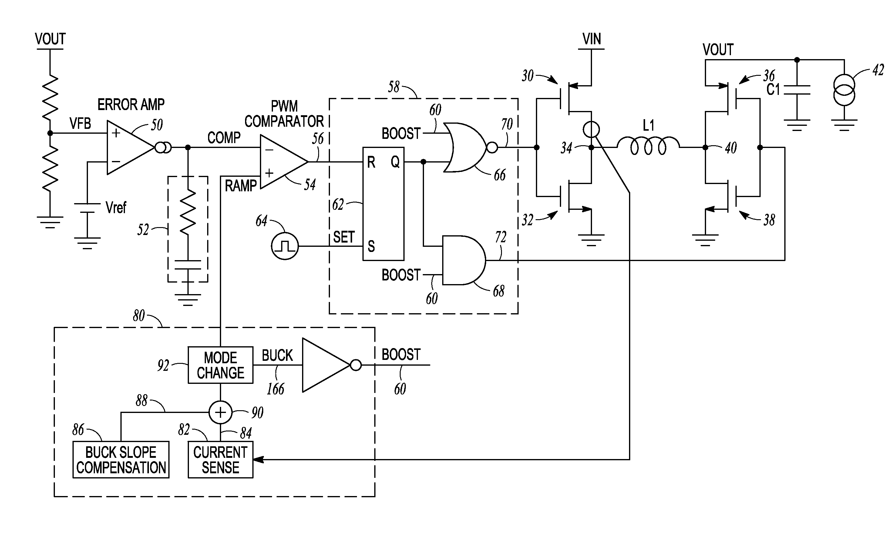
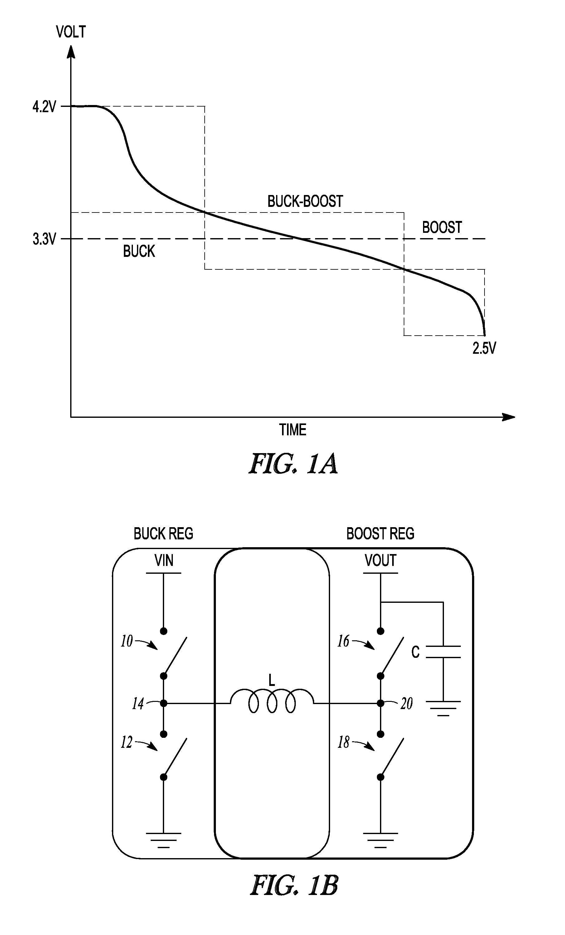
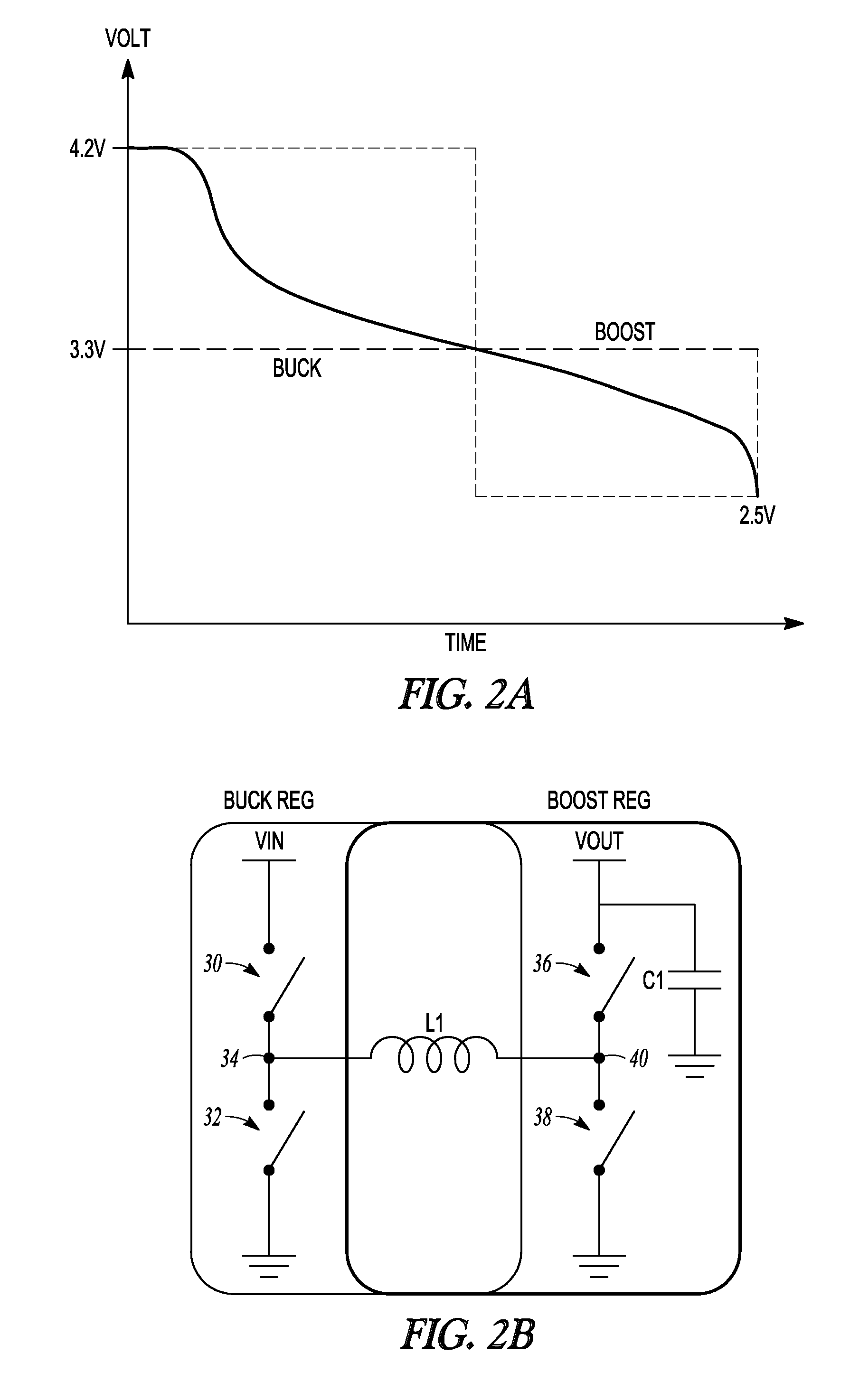
[0028]A diagram illustrating switching converter operating mode vs. input voltage for a windowless buck-boost switching converter per the present invention is shown in FIG. 2a. The present converter architecture has only 2 operating modes—buck and boost—which serves to reduce efficiency problems found in conventional buck-boost converters, while also minimizing output discontinuities. The converter uses an H-bridge configuration as shown in FIG. 2b, with two switching elements 30, 32 connected together at a node 34 and between VIN and a circuit common point, and two switching elements 36, 38 connected together at a node 40 between VOUT and the circuit common point. An inductor L1 is connected between nodes 34 and 40, and a filter capacitor C1 is connected between VOUT and circuit common. For the present converter, in buck mode, switching element 36 is closed and switching elements 30 and 32 are switched on and off in complementary fashion, typically with pulse-width modulated (PWM) ...


PUM


Abstract

A “windowless” H-bridge buck-boost switching converter includes a regulation circuit with an error amplifier which produces a ‘comp’ signal, a comparison circuit which compares ‘comp’ with a ‘ramp’ signal, and logic circuitry which receives the comparison circuit output and a mode control signal indicating whether the converter is to operate in buck mode or boost mode and operates the primary or secondary switching elements to produce the desired output voltage in buck or boost mode, respectively. A ‘ramp’ signal generation circuit operates to shift the ‘ramp’ signal up by a voltage Vslp(p−p)+Vhys when transitioning from buck to boost mode, and to shift ‘ramp’ back down by Vslp(p−p)+Vhys when transitioning from boost to buck mode, thereby enabling the converter to operate in buck mode or boost mode only, with no need for an intermediate buck-boost region.

Description

RELATED APPLICATIONS[0001]This application claims the benefit of provisional patent application No. 61 / 704,195 to Hirohisa Tanabe, filed Sep. 21, 2012, and to provisional patent application No. 61 / 772,038 to Hirohisa Tanabe, filed Mar. 4, 2013.BACKGROUND OF THE INVENTION[0002]1. Field of the Invention[0003]This invention relates generally to switching power converters, and more particularly to buck-boost switching converters.[0004]2. Description of the Related Art[0005]A switching converter receives an input voltage VIN and produces an output voltage VOUT. One type of switching converter known as a ‘buck-boost’ converter is capable of operating in either a buck mode in which the output voltage produced is less than the input voltage (VOUT<VIN), a boost mode in which VOUT>VIN, or in a buck-boost mode in which VOUT is nearly equal to VIN.[0006]One suitable application of a buck-boost converter is in a battery-powered system, in which input voltage VIN decreases over time; this i...

Claims


Application Information

Patent Timeline
Patent Type & Authority Applications(United States)
IPC IPC(8): H02M3/158
CPCH02M3/1582
Inventor TANABE, HIROHISA
Owner ANALOG DEVICES INT UNLTD
Why Eureka
Try Eureka