Ink-Jet Head And Ink-Jet Drawing Device Provided with Same

Active Publication Date: 2014-04-03
KONICA MINOLTA INC
View PDF2 Cites 7 Cited by
  • Summary
  • Abstract
  • Description
  • Claims
  • Application Information

AI Technical Summary

Benefits of technology

[0012]In the present invention, the space to which the first electrode and the second electrode are exposed is hermetically sealed by adhering the head substrate and the wiring substrate through the adhesive layer, and the hermetically sealed space is in a vacuum state or contains the predetermined amount of water or less. Thus, it is possible to prevent the electrical connec

Problems solved by technology

However, in the ink-jet head in which a plurality of rows of nozzles are arranged to perform drawing with higher definition, the highly dense arrangement of the nozz

Method used


Image

  • Ink-Jet Head And Ink-Jet Drawing Device Provided with Same
  • Ink-Jet Head And Ink-Jet Drawing Device Provided with Same
  • Ink-Jet Head And Ink-Jet Drawing Device Provided with Same

Examples


Example

[0017]An embodiment of the present invention will be described with reference to accompanying drawings.

[0018](About an Ink-Jet Head)

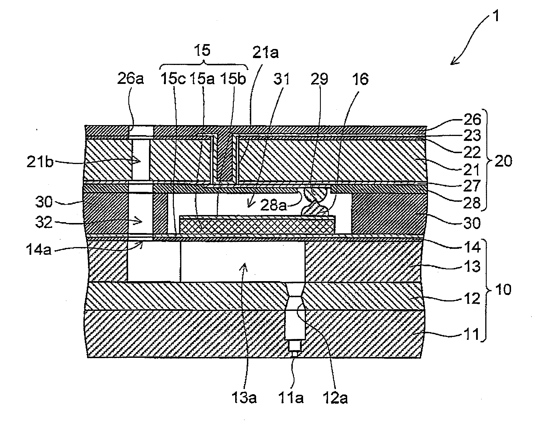
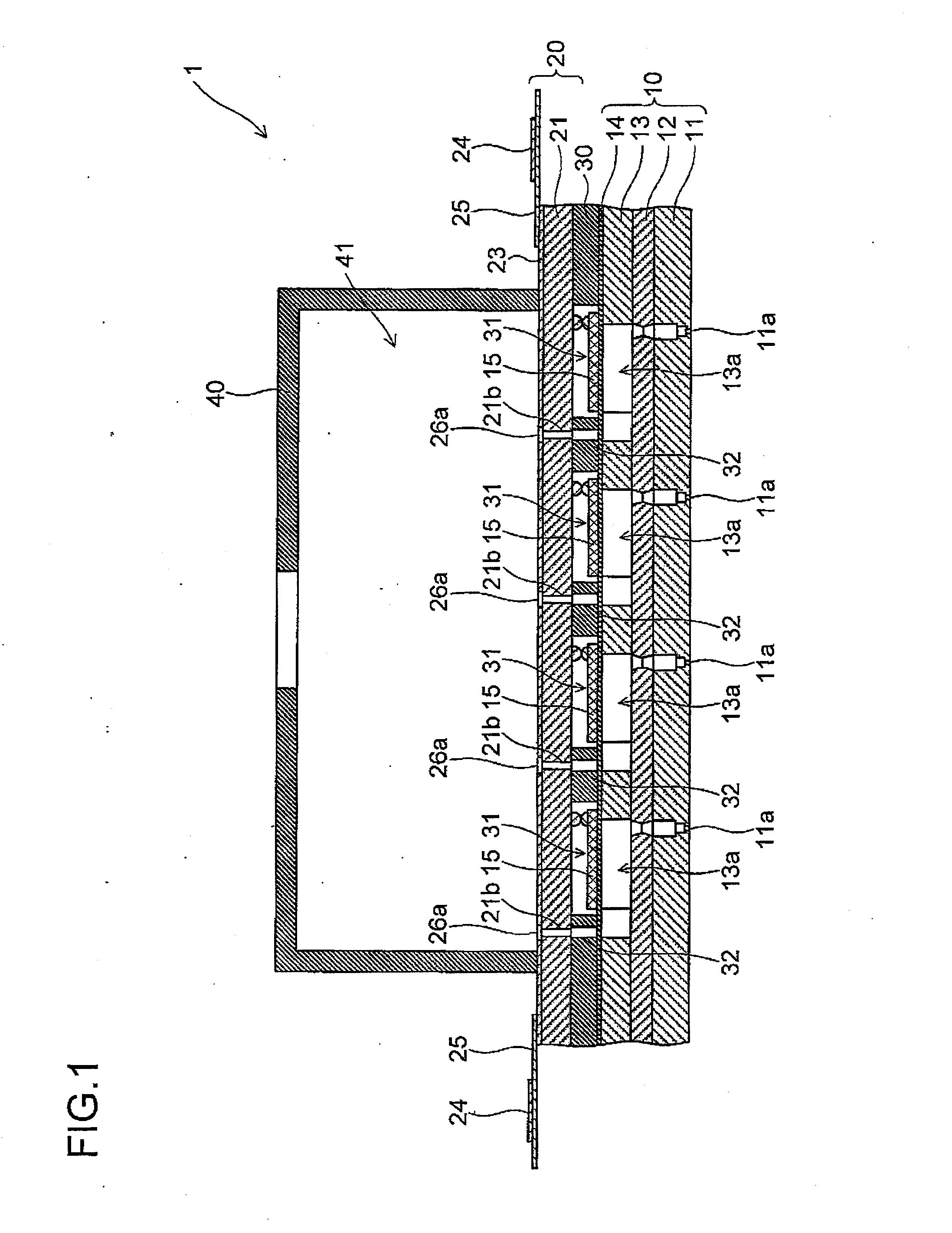
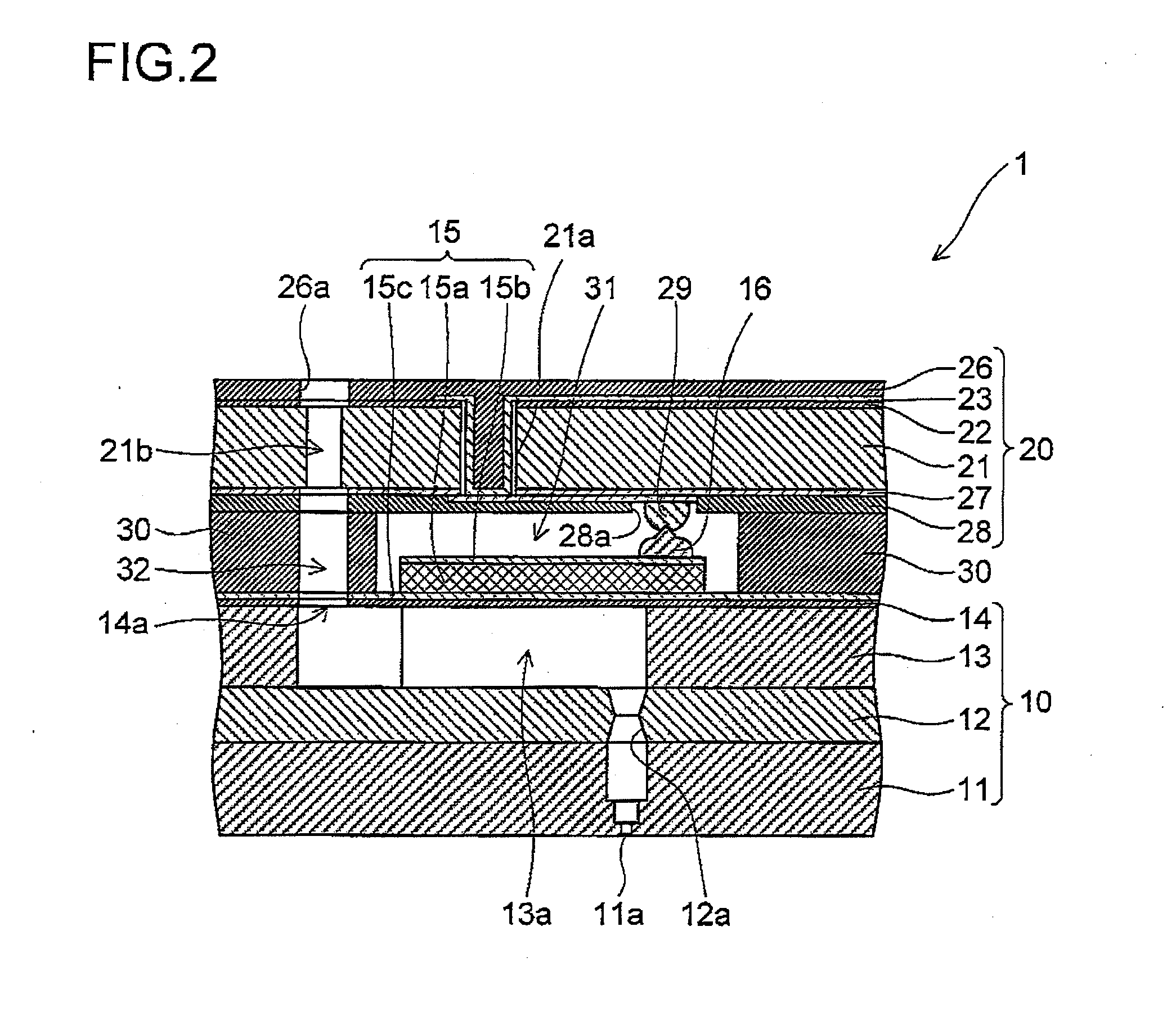
[0019]FIG. 1 is a cross-sectional view showing the schematic configuration of an ink-jet head 1 according to the present embodiment. FIG. 2 is a cross-sectional view showing an enlarged main portion of the ink-jet head 1. The ink-jet head 1 is formed by stacking a head substrate 10 and a wiring substrate 20 through an adhesive resin layer 30 and integrating them. On the upper surface of the wiring substrate 20, a box-shaped manifold 40 is provided; the interior of the manifold 40 forms a common ink chamber 41 where an ink is stored with the wiring substrate 20.

[0020](About the Head Substrate)

[0021]The head substrate 10 includes, from the side of the bottom layer, a nozzle plate 11 formed with a Si (silicon) substrate, an intermediate plate 12 formed with a glass substrate, a pressure chamber plate 13 formed with Si of a support layer of a SOI (silicon o...


PUM


Abstract

An actuator included in a head substrate of an ink-jet head receives, with an electrode on the surface of the actuator, power fed from the wiring of a wiring substrate arranged opposite the head substrate. A first electrode of the wiring substrate is electrically connected to the wiring, and protrudes to the side of the head substrate. A second electrode is electrically connected to the electrode on the surface of the actuator, protrudes to the side of the wiring substrate and is electrically connected to the first electrode. The head substrate and the wiring substrate are adhered to each other through an adhesive layer such that a space to which the first electrode and the second electrode are exposed is hermetically sealed. The hermetically sealed space is in a vacuum state or is filled with a gas containing a predetermined amount of water or less.

Description

TECHNICAL FIELD[0001]The present invention relates to an ink-jet head in which a head substrate having an actuator that discharges ink from a pressure chamber and a wiring substrate for feeding power to the actuator are arranged opposite each other and to an ink-jet drawing device which performs drawing with such an ink-jet head.BACKGROUND ART[0002]Conventionally, an ink-jet drawing device is developed that drives an actuator to discharge ink within a pressure chamber through a nozzle and thereby performs drawing (image formation) on a recording member. In the ink-jet drawing device as described above, in order to realize drawing with more accuracy and higher definition, it is required to further densely arrange the nozzles in the ink jet head. For example, it is possible to realize the highly dense arrangement of the nozzles and perform drawing with higher definition by arranging a plurality of rows of nozzles and displacing the nozzles a half pitch for each row to arrange them.[00...

Claims


Application Information

Patent Timeline
IPC IPC(8): B41J2/14
CPCB41J2/14201B41J2/055B41J2/14233B41J2202/11B41J2002/14491
Inventor KITAMURA, KENMIYAI, MITSUYOSHIMATSUDA, SHINYA
Owner KONICA MINOLTA INC
Why Eureka
Try Eureka