Integrated Blower Diffuser and Heat Exchanger for Electronics Enclosure

a technology of electronics enclosure and diffuser, which is applied in the direction of ventilation panels with screening provisions, cooling/ventilation/heating modifications, basic electric elements, etc., can solve the problems of not being proposed to incorporate a blower diffuser into an enclosure, the electronics need to handle increasingly high levels of cooling, and the transformer is difficult to adequately cool

Active Publication Date: 2014-04-03
HAMILTON SUNDSTRAND CORP
View PDF10 Cites 10 Cited by
  • Summary
  • Abstract
  • Description
  • Claims
  • Application Information

AI Technical Summary

Problems solved by technology

Electronics generate heat, and systems for cooling of the electronics need to handle increasingly high levels of cooling, particularly as the complexity of the electronic controls increases.
Adequately cooling these electronics and the transformer has proven challenging.
However, this blower diffuser has not been proposed to be incorporated into an enclosure in a way to adequately cool the electronics, as mentioned above.

Method used


Image

  • Integrated Blower Diffuser and Heat Exchanger for Electronics Enclosure
  • Integrated Blower Diffuser and Heat Exchanger for Electronics Enclosure
  • Integrated Blower Diffuser and Heat Exchanger for Electronics Enclosure

Examples


Embodiment Construction

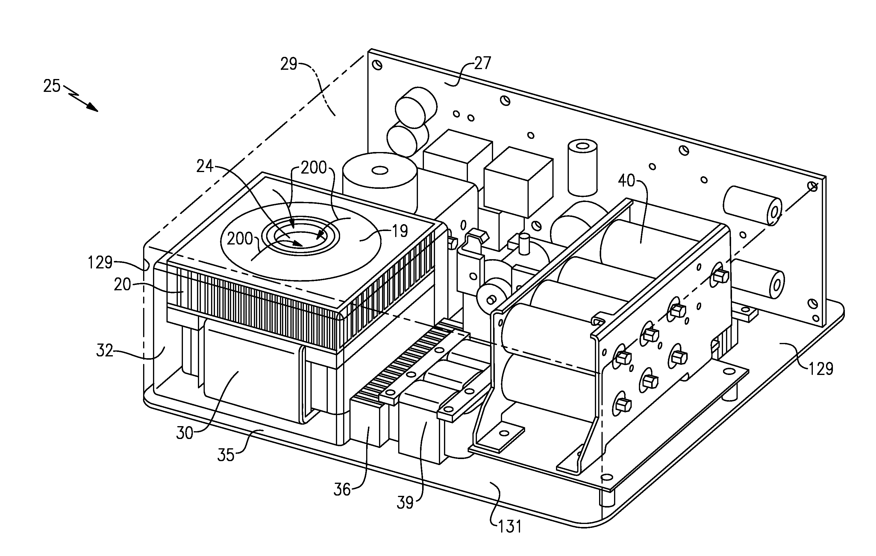
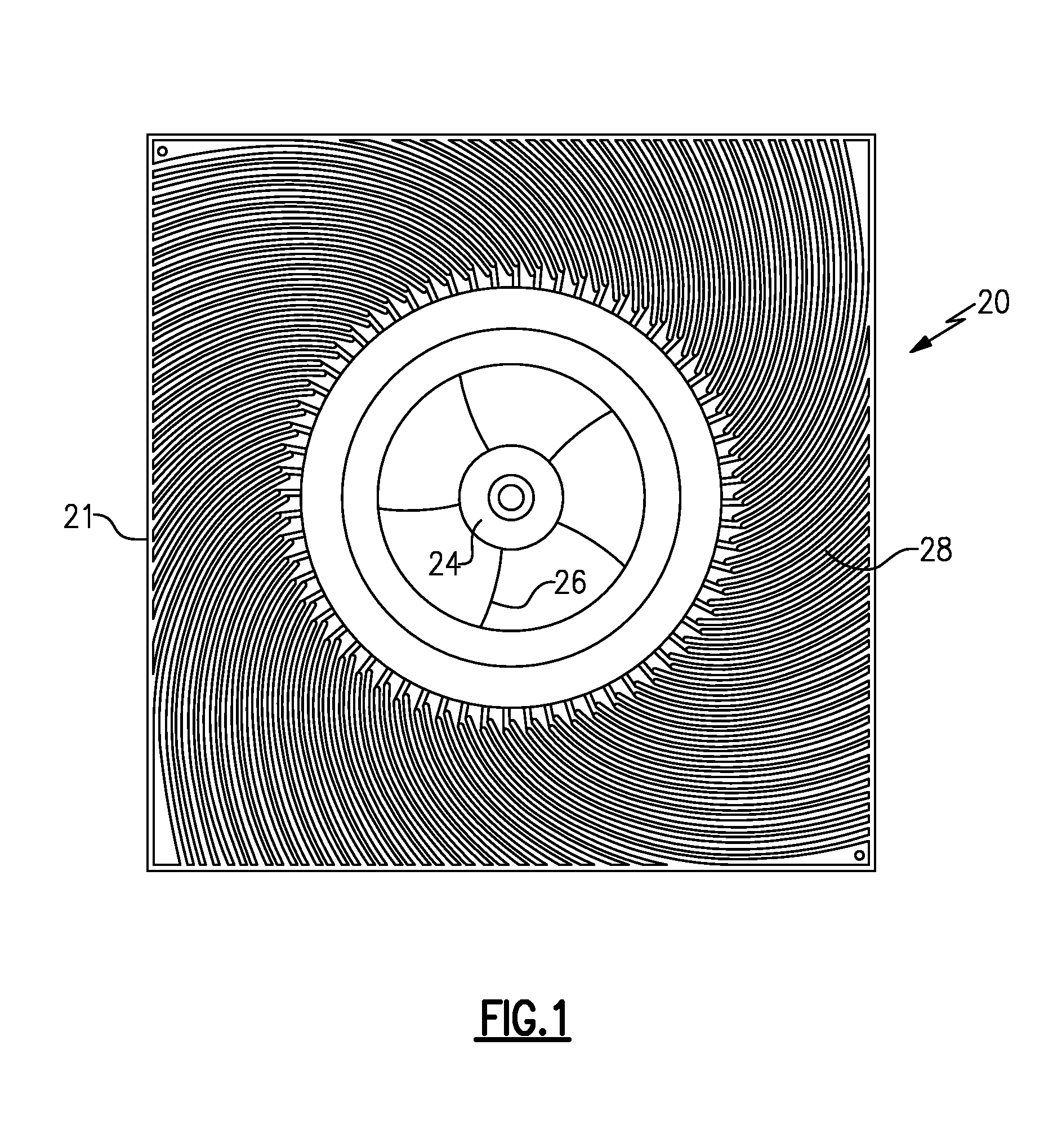
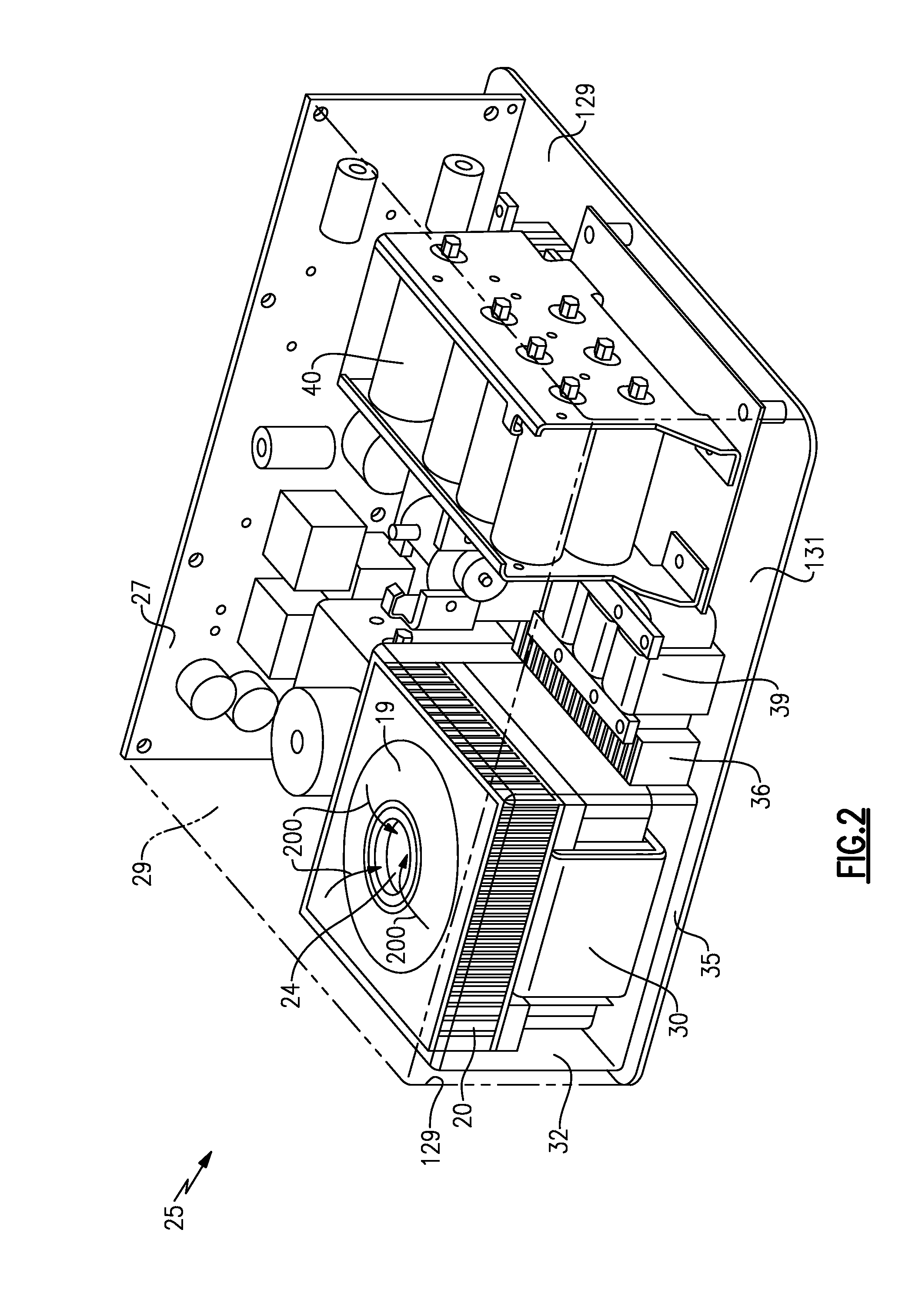
[0012]FIG. 1 shows a blower diffuser 20 having an inlet 24 leading to a bladed impeller 26. A motor drives a bladed impeller 26 to take air in axially into inlet 24 (as shown at 200 in FIG. 2), and directs the air radially outwardly. A plurality of guide vanes 28 are positioned about the circumference of the impeller 26 to provide a diffuser and heat transfer fins. Thus, the blower diffuser 20 also functions as a heat exchanger.

[0013]FIG. 1 shows the footprint of the blower diffuser 20. As can be appreciated, the blower diffuser 20 has a relatively square outer periphery 21. Of course, other shapes may be utilized.

[0014]FIG. 2 shows an electronics enclosure 25. As shown in FIG. 2, there is actually a cover 19 on blower diffuser 20 (not illustrated in FIG. 1), which sits around the inlet 24, and encloses the bladed impeller 26. The blower diffuser 20 is positioned within the enclosure 25. In this Figure, a rear wall 27 is shown. A top wall 29, side walls 129, and front wall 131 are s...


PUM


Abstract

An electronics enclosure has a blower and diffuser received within an enclosure. Electronic components are also received within the enclosure. The blower diffuser is positioned in contact with at least one of the electronic components. A shroud surrounds the blower diffuser and the at least one electronic component, and is spaced from an outer surface of the at least one electronic component. An opening is formed through the shroud, such that air can be driven within the shroud from the blower diffuser, and across at least one electronic component, and then outwardly of the opening. A heat exchanger is positioned in the path of air leaving the opening.

Description

BACKGROUND OF THE INVENTION[0001]This invention was made with government support under Contract No. W31P4Q-09-C-0067 awarded by the United States Army. The Government has certain rights in this invention.BACKGROUND OF THE INVENTION[0002]This application relates to a unique cooling arrangement for cooling inside of an electronics enclosure.[0003]Modern electronics provide control for increasingly complex operations. Electronics generate heat, and systems for cooling of the electronics need to handle increasingly high levels of cooling, particularly as the complexity of the electronic controls increases.[0004]One particular type of electronic control is a transformer. Typically, the transformer may be mounted within a housing with additional electronics. Adequately cooling these electronics and the transformer has proven challenging.[0005]The assignee of the present application has developed a blower diffuser which provides a high volume of cooling air flow in a relatively small packa...

Claims


Application Information

Patent Timeline
Patent Type & Authority Applications(United States)
IPC IPC(8): H05K7/20
CPCH05K7/20154H05K7/20145H01F27/025H01F27/085H05K9/0041
Inventor TURNEY, JOSEPHST. ROCK, BRIANWHITON, JOHN H.
Owner HAMILTON SUNDSTRAND CORP
Why Eureka
Try Eureka