Dental implant positioning system

a positioning system and dental implant technology, applied in dentistry, boring tools, medical science, etc., can solve the problems of reducing precision, affecting the accuracy of dental implants, and reducing the accuracy of surgical procedures, so as to prevent binding and stripping of threads

Inactive Publication Date: 2014-04-03
CARMICHAEL ROBERT P +1
View PDF9 Cites 29 Cited by
  • Summary
  • Abstract
  • Description
  • Claims
  • Application Information

AI Technical Summary

Benefits of technology

[0019]The lead 2 or 3 threads of the proximal intermediate portion of the guided drill or the proximal portion of the drive shaft and / or the distal 2 or 3 threads of the guide may advantageously be tapered to assist in preventing binding and stripping of the threads.

Problems solved by technology

This means that the surgical procedure itself involves a plurality of steps, all of which are conducted at relatively slow speeds, which thus prolong the surgical procedure and decrease precision.
One of the problems that can arise in this situation is that the template provides only a rough or imprecise guide as to where the dentist should place the implant.
Thus, because the dentist is given some leeway in deciding where the implant is to be placed, the location of the implant is not controlled and may not reflect the position intended.
Moreover, the design of the prosthesis may be non-ideal in terms of strength, esthetic appearance or the biological response it provokes.

Method used


Image

  • Dental implant positioning system
  • Dental implant positioning system
  • Dental implant positioning system

Examples


Embodiment Construction

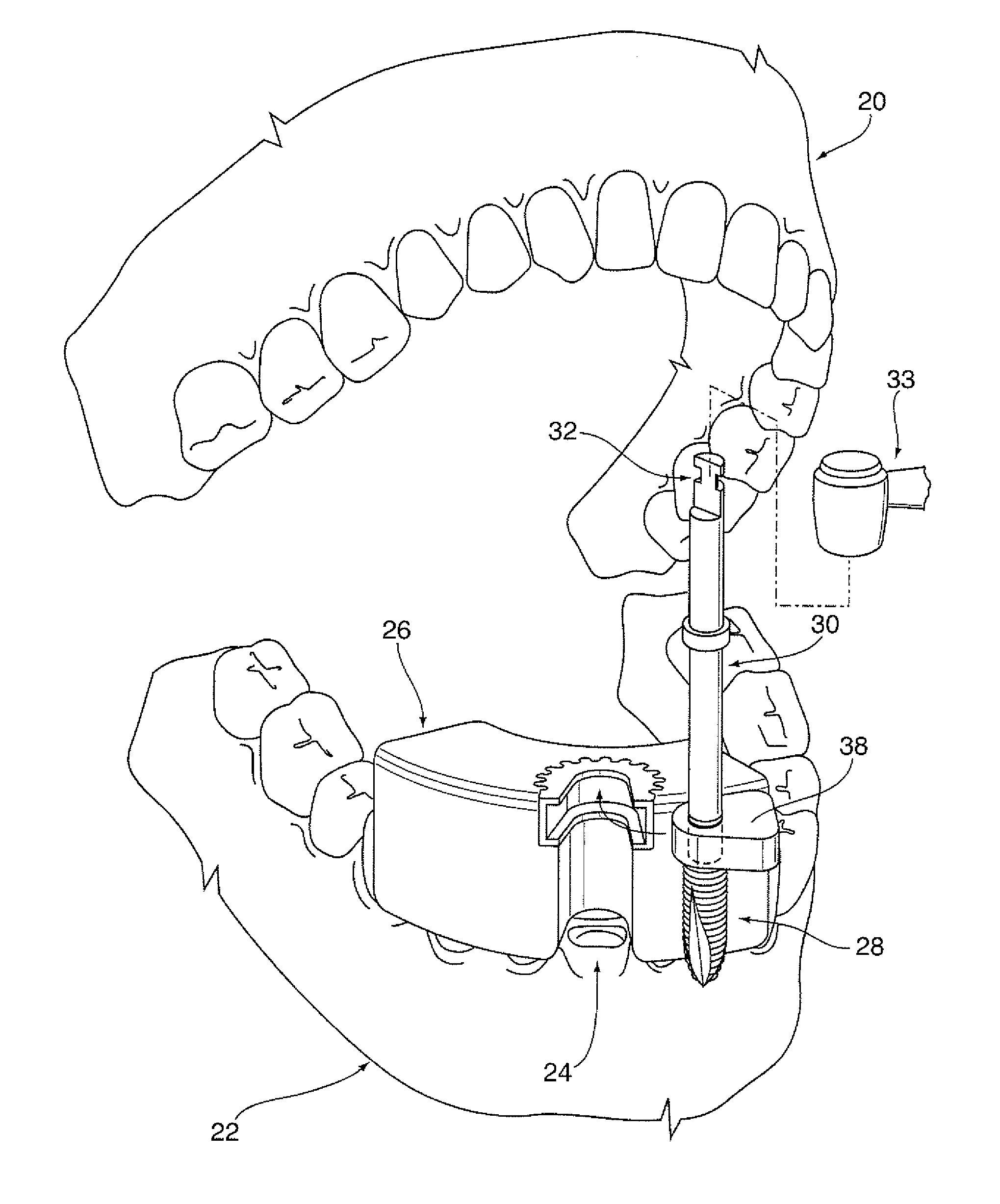
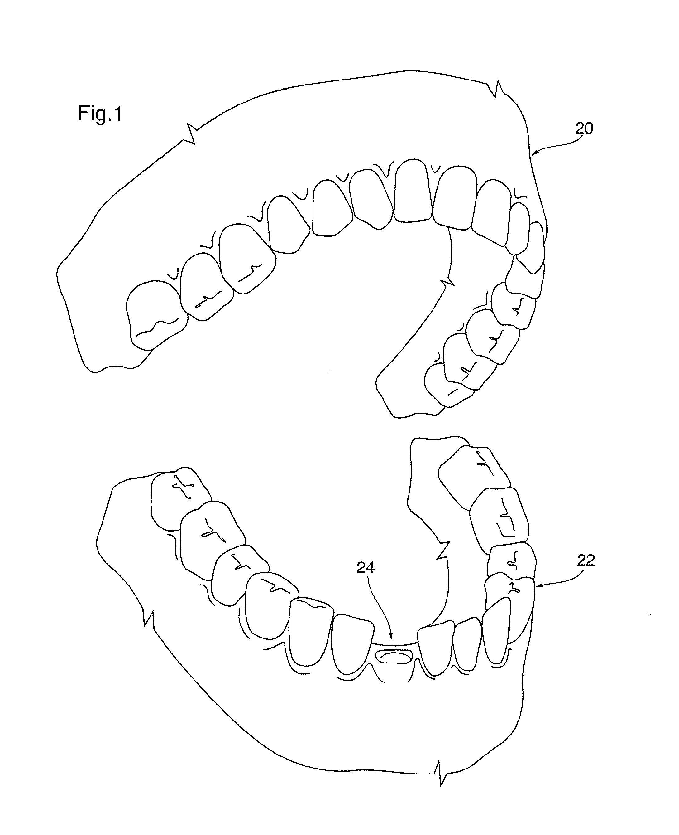
[0033]Referring first to FIG. 1, upper and lower jaws 20 and 22 respectively of a patient are shown in an open condition as for installation of a dental implant. The intended location of the implant is indicated at 24.

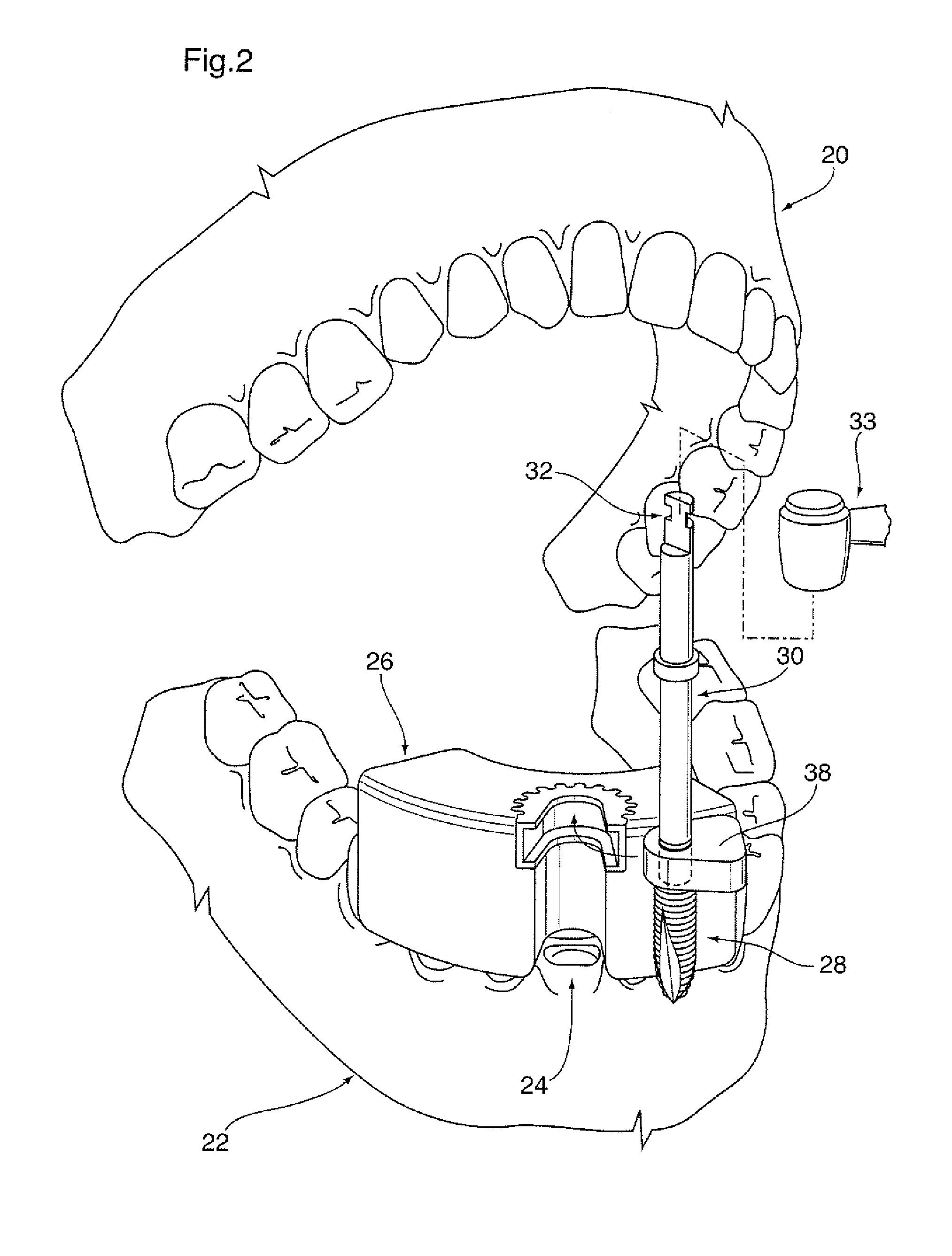
[0034]FIG. 2 shows components of the system of the invention in place on the lower jaw 22.

[0035]A surgical template is illustrated diagrammatically at 26. The template will be made by technicians in a dental laboratory prior to commencement of the implant installation procedure. The template will have been molded closely to a cast of the patient's jaw at the location at which the implant is to be installed.

[0036]The implant itself is shown at 28 and is a self-drilling, self-tapping dental implant, for example of the type shown in U.S. Pat. No. 7,008,227 supra. The implant is threaded onto the leading lower end of a drive shaft 30. Alternative connection means such as a Torx drive socket may be used to attach the implant to the drive shaft. Drive shaft 30 extends about ...


PUM


Abstract

A system is disclosed for installing a dental implant in a jawbone of a patient. The system includes a threaded drive shaft rotatable about an axis and guide means for supporting the drive shaft with its axis oriented in a path along which the implant is to be installed. The guide means has a threaded bore for receiving a drive shaft and an opening which extends parallel to the axis of the drive shaft and opens radially outwardly from the bore. The drive shaft can then be engaged with and disengaged from the guide means by radial displacement of the shaft parallel to its axis. A drill is adapted to be releasably coupled to a leading end portion of the drive shaft and may be a self-drilling implant. Means is provided for rotating the drive shaft in a direction to cause the drill to penetrate the jawbone of the patient.

Description

CROSS-REFERENCE TO RELATED APPLICATION[0001]This application claims benefit from U.S. Provisional Application No. 61 / 707,121 filed Sep. 28, 2012 which is incorporated herein by reference in its entirety.FIELD[0002]This invention relates to the field of dentistry. In particular, the invention relates to the positioning of dental implants or drills, including self-drilling, self-tapping dental implants.INTRODUCTION[0003]The procedure required to place a dental implant in a patient's jawbone typically involved the use of as many as five drills followed by a tap, all of which must be operated at relatively low speed. In addition, up to five guide pins may be used to assess angulation throughout the drilling procedure. This means that the surgical procedure itself involves a plurality of steps, all of which are conducted at relatively slow speeds, which thus prolong the surgical procedure and decrease precision. In addition, the procedure involved the use of many components including the...

Claims


Application Information

Patent Timeline
Patent Type & Authority Applications(United States)
IPC IPC(8): A61C8/00
CPCA61C8/0089A61C1/084A61C8/0024
Inventor CARMICHAEL, ROBERT P.SPITZ, WARREN
Owner CARMICHAEL ROBERT P
Why Eureka
Try Eureka