Heat exchanger

a heat exchanger and heat exchanger technology, applied in the direction of heat exchanger fastening, lighting and heating apparatus, stationary conduit assemblies, etc., can solve the problem of increasing the design space of the inlet pipe, and achieve the effect of improving the refrigerant distribution structur

Inactive Publication Date: 2014-04-10
SAMSUNG ELECTRONICS CO LTD
View PDF18 Cites 14 Cited by
  • Summary
  • Abstract
  • Description
  • Claims
  • Application Information

AI Technical Summary

Benefits of technology

[0008]Therefore, it is an aspect of the present disclosure to provide a heat exchanger having one inlet pipe and one outlet pipe and having an improved refrigerant distribution structure.

Problems solved by technology

However, because an increase in the number of inlet pipes increases cost design space, a structure in which only one inlet pipe is used while distribution of the refrigerant is improved has been researched.

Method used


Image

  • Heat exchanger
  • Heat exchanger
  • Heat exchanger

Examples


Embodiment Construction

[0077]Reference will now be made in detail to the embodiments of the present disclosure, examples of which are illustrated in the accompanying drawings, wherein like reference numerals refer to like elements throughout.

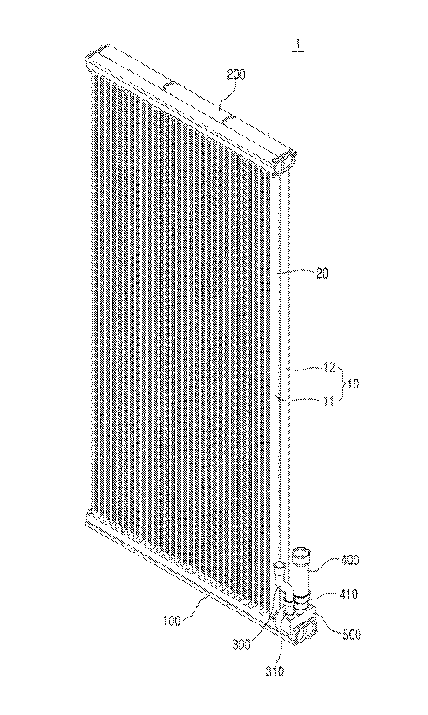
[0078]FIG. 1 is a perspective view illustrating the exterior of a heat exchanger according to an embodiment of the present disclosure.

[0079]Referring to FIG. 1, a heat exchanger 1 according to an embodiment of the present disclosure includes a plurality of tubes 10 in which a refrigerant flows and is heat-exchanged with air outside the heat exchanger, heat-exchanging fins 20 that contact the plurality of tubes 10 to increase a heat transfer area with air outside the heat exchanger 1, a first header 100 and a second header 200 in which the plurality of tubes 10 communicate with one another, an inlet pipe 300 through which a refrigerant outside the heat exchanger 1 flows into the heat exchanger 1, an outlet pipe 400 through which the refrigerant flows out of the heat ex...


PUM


Abstract

A heat exchanger having an improved distribution structure in which one inlet pipe is connected to a header which is partitioned into a first sub-chamber in which a refrigerant flows through the inlet pipe and a second sub-chamber in which tubes communicate with each other, and a distribution pipe is installed at the header and causes the first sub-chamber and the second sub-chamber to communicate so that the refrigerant in the first sub-chamber can be distributed to the tubes. The distribution pipe can pass through and can be combined with a partitioning baffle that is combined with the header to partition a chamber of the header into the first sub-chamber and the second sub-chamber.

Description

CROSS-REFERENCE TO RELATED APPLICATIONS[0001]This application claims the priority benefit of Korean Patent Application No. 10-2012-0111721 filed on Oct. 9, 2012, and Korean Patent Application No. 10-2013-0042780 filed on Apr. 18, 2013 in the Korean Intellectual Property Office, the disclosures of which are incorporated herein by reference.BACKGROUND[0002]1. Field[0003]The following description relates to a heat exchanger, and more particularly, to a heat exchanger having an improved refrigerant distribution structure.[0004]2. Description of the Related Art[0005]In general, a heat exchanger is a device that exchanges heat from a refrigerant with air outside the heat exchanger by using a tube in which the refrigerant flows and is heat-exchanged with air outside the heat exchanger, heat-exchanging fins that contact the tube to increase a heat dissipation area, and a header in which both ends of the tube communicate with each other. The heat exchanger may include an evaporator or a cond...

Claims


Application Information

Patent Timeline
Patent Type & Authority Applications(United States)
IPC IPC(8): F28F9/02
CPCF28F9/0202F28F9/0204F28F9/0253F28F9/0273F28D1/05391F28D2021/0068F28F9/0224F28F2275/04F28F2220/00
Inventor SEO, KANG TAEBAEK, YONG KIHA, SEUNG HEEGAKU, HAYASE
Owner SAMSUNG ELECTRONICS CO LTD
Why Eureka
Try Eureka