
Ray cone hierarchy renderer

a hierarchy and renderer technology, applied in the field of computer animation, can solve problems such as greater computational and memory costs

Active Publication Date: 2014-04-10
DISNEY ENTERPRISES INC
View PDF4 Cites 12 Cited by
  • Summary
  • Abstract
  • Description
  • Claims
  • Application Information

AI Technical Summary

Benefits of technology

The patent is about a system and method for organizing rays of light into groups based on their directions. These groups can then be ranked based on their origin and a hierarchy of bounding cones can be generated. The resulting structure can be used to create a bounding cone hierarchy that intersects with other scene hierarchies. The technical effect of this system is to improve the efficiency and accuracy of identifying and organizing relevant rays of light in a way that reduces the amount of data needed to store and analyze them.

Problems solved by technology

The technique is capable of producing a very high degree of visual realism, usually higher than that of typical scanline rendering methods, but at greater computational and memory costs.

Method used


Image

  • Ray cone hierarchy renderer
  • Ray cone hierarchy renderer
  • Ray cone hierarchy renderer

Examples


Embodiment Construction

[0014]Tracing rays or cone, one at a time, is memory and processing intensive. Even with a scene hierarchy, large numbers of rays require high amounts of memory bandwidth to traverse the queries across scene nodes and perform the large number of intersection computations.

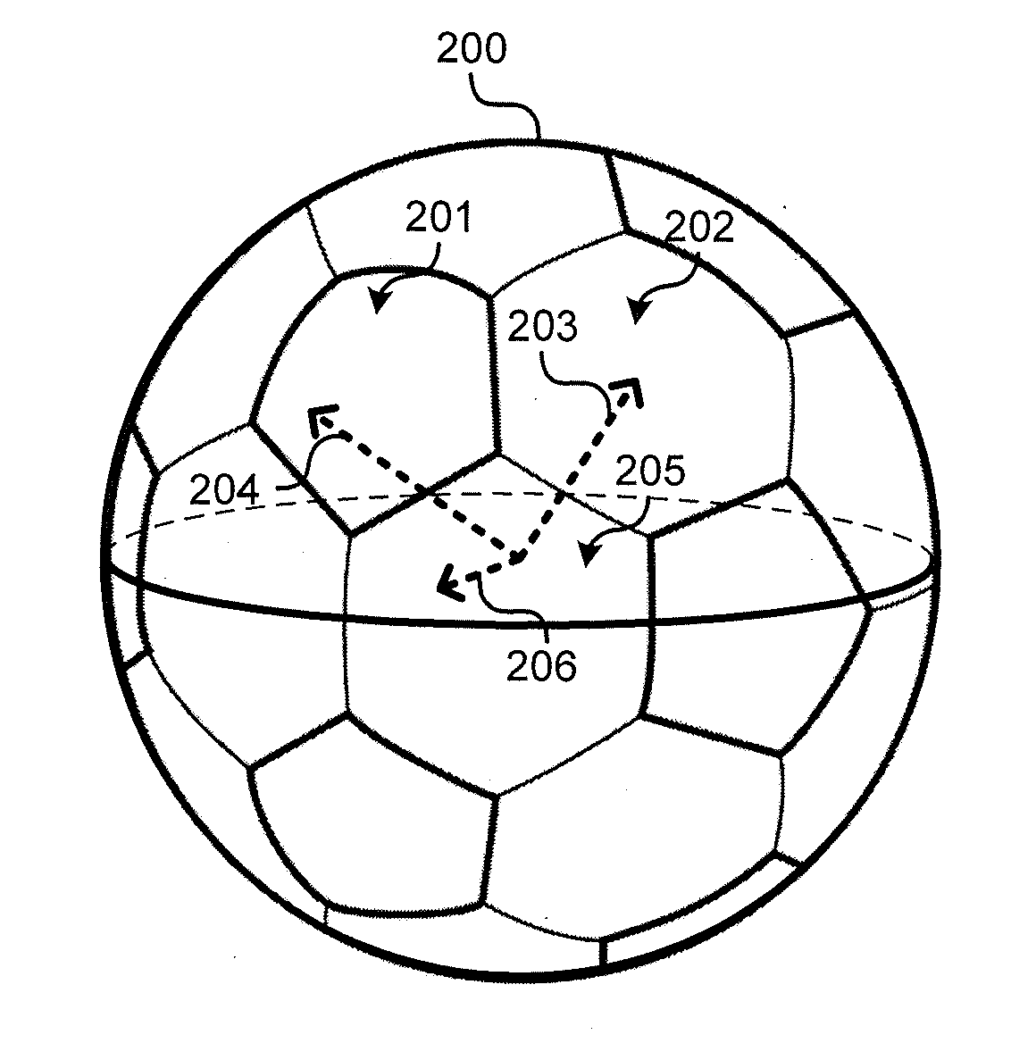
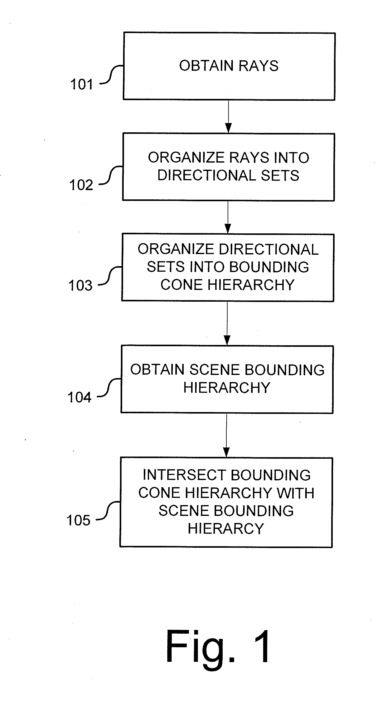
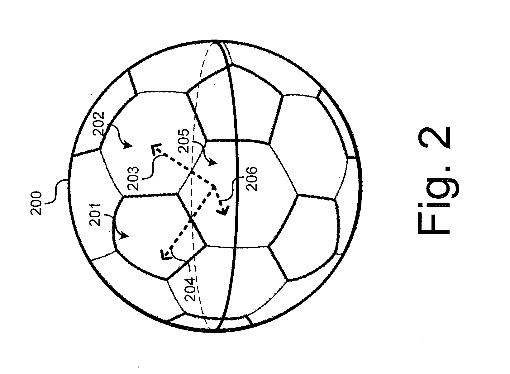
[0015]FIG. 1 illustrates an example method for intersecting rays with a scene in a ray tracing scene rendering system. In step 101, rays are obtained for processing. This may include obtaining rays 101 by generating camera rays, generating reflection rays, generating refraction rays, generating shadow rays, generating light rays, or generating any other rays utilized during conventional ray tracing rendering processes. The obtained rays may be a single ray type or a mixture of different ray types. In some cases, the step of obtaining rays 101 includes loading all of the rays that will be used in the method into memory. In other cases, subsets of the entire set of rays may be loaded into memory for iterative processi...


PUM


Abstract

Some aspects of the disclosure include systems and methods for grouping rays into sets according to their directions. In some cases, the rays of the directional sets may then be organized into a hierarchy according to their origins and bounding cones are generated for the hierarchy nodes. The resulting bounding cone hierarchy may be intersected with a bounding volume hierarchy or other scene hierarchy.

Description

CROSS-REFERENCE TO RELATED APPLICATION[0001]This application claims the benefit of U.S. Provisional Application No. 61 / 710,614, which is hereby incorporated in its entirety.TECHNICAL FIELD[0002]The present application relates generally to computer animation, and more particularly, some embodiments relate to ray tracing.DESCRIPTION OF THE RELATED ART[0003]Ray tracing is a technique for generating an image by tracing the path of light through pixels in an image plane and simulating the effects of its encounters with virtual objects. The technique is capable of producing a very high degree of visual realism, usually higher than that of typical scanline rendering methods, but at greater computational and memory costs.BRIEF SUMMARY[0004]Some aspects of the disclosure include systems and methods for grouping rays into sets according to their directions. In some cases, the rays of the directional sets may then be organized into a hierarchy according to their origins and bounding cones are ...

Claims


Application Information

Patent Timeline
Patent Type & Authority Applications(United States)
IPC IPC(8): G06T15/00G06T1/00
CPCG06T15/06
Inventor BURLEY, BRENTEISENACHER, CHRISTIANNICHOLS, GREGORYSELLE, ANDREW
Owner DISNEY ENTERPRISES INC
Learn More