Array microphone device and gain control method

a microphone device and gain control technology, applied in the direction of transducer details, electrical transducers, electrical apparatus, etc., can solve the problems of low performance of array microphone devices, long time to converge gain, and fluctuation of sound, so as to achieve high-speed convergence and keep sound quality

Active Publication Date: 2014-04-10
PANASONIC INTELLECTUAL PROPERTY MANAGEMENT CO LTD
View PDF5 Cites 12 Cited by
  • Summary
  • Abstract
  • Description
  • Claims
  • Application Information

AI Technical Summary

Benefits of technology

[0018]According to the present invention, it is possible to keep sound q...

Problems solved by technology

In the conventional array microphone device, however, when a gain is updated with large amount per hour at the time of amplifying or attenuating a signal from each of the microphone units, this may cause an auditory fluctuation of sound and degradation in distortion rate.
Furthermore, in the case where the updated amount of gain once becomes large, this requires a long time to converge the gain in case of the updated amount of gain per hour being made with a tiny amount.
Such a circumstances bring about lower performance of the array microphone device at the time of start-up, which might be caused by directivity synthe...

Method used


Image

  • Array microphone device and gain control method
  • Array microphone device and gain control method
  • Array microphone device and gain control method

Examples


first embodiment

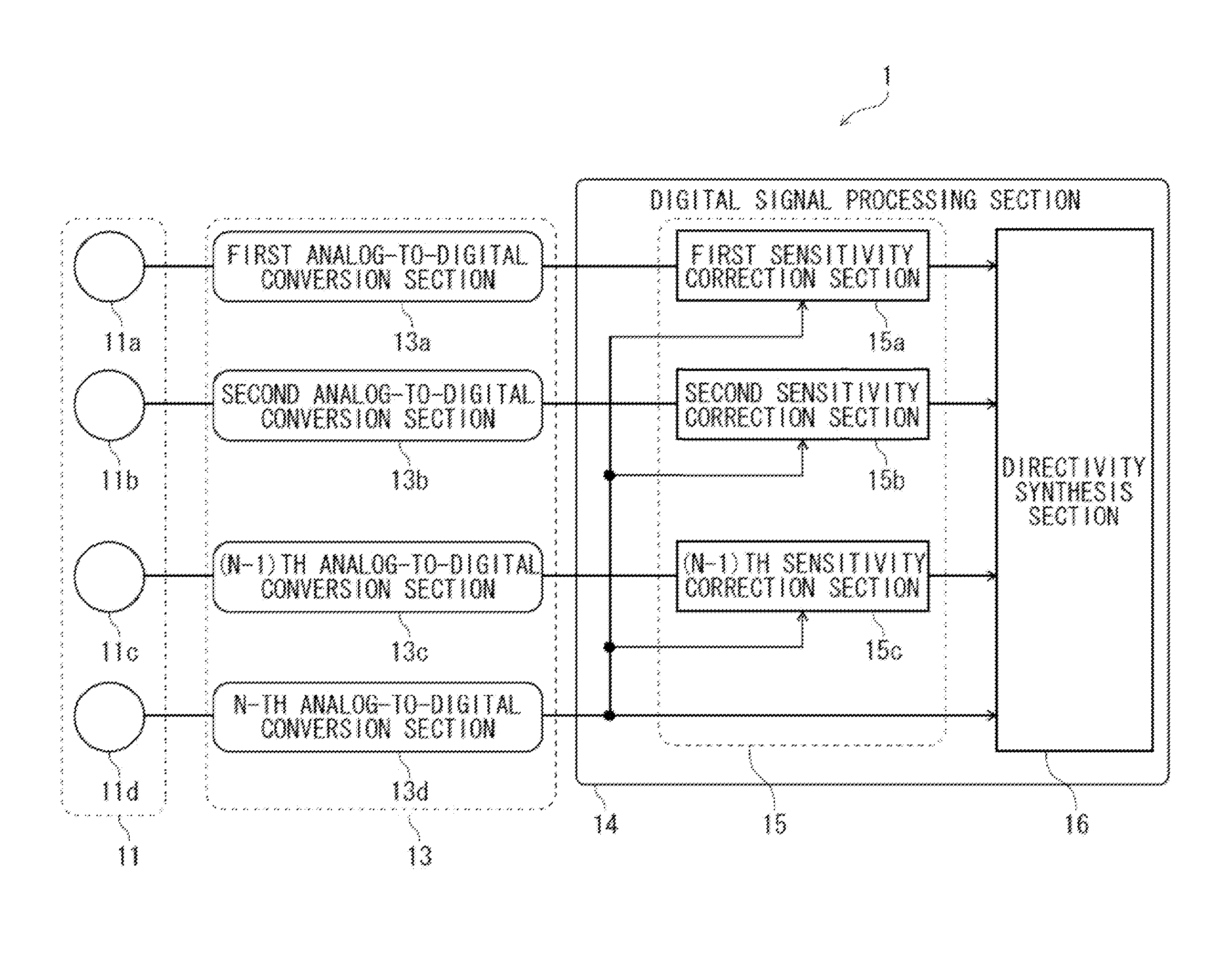
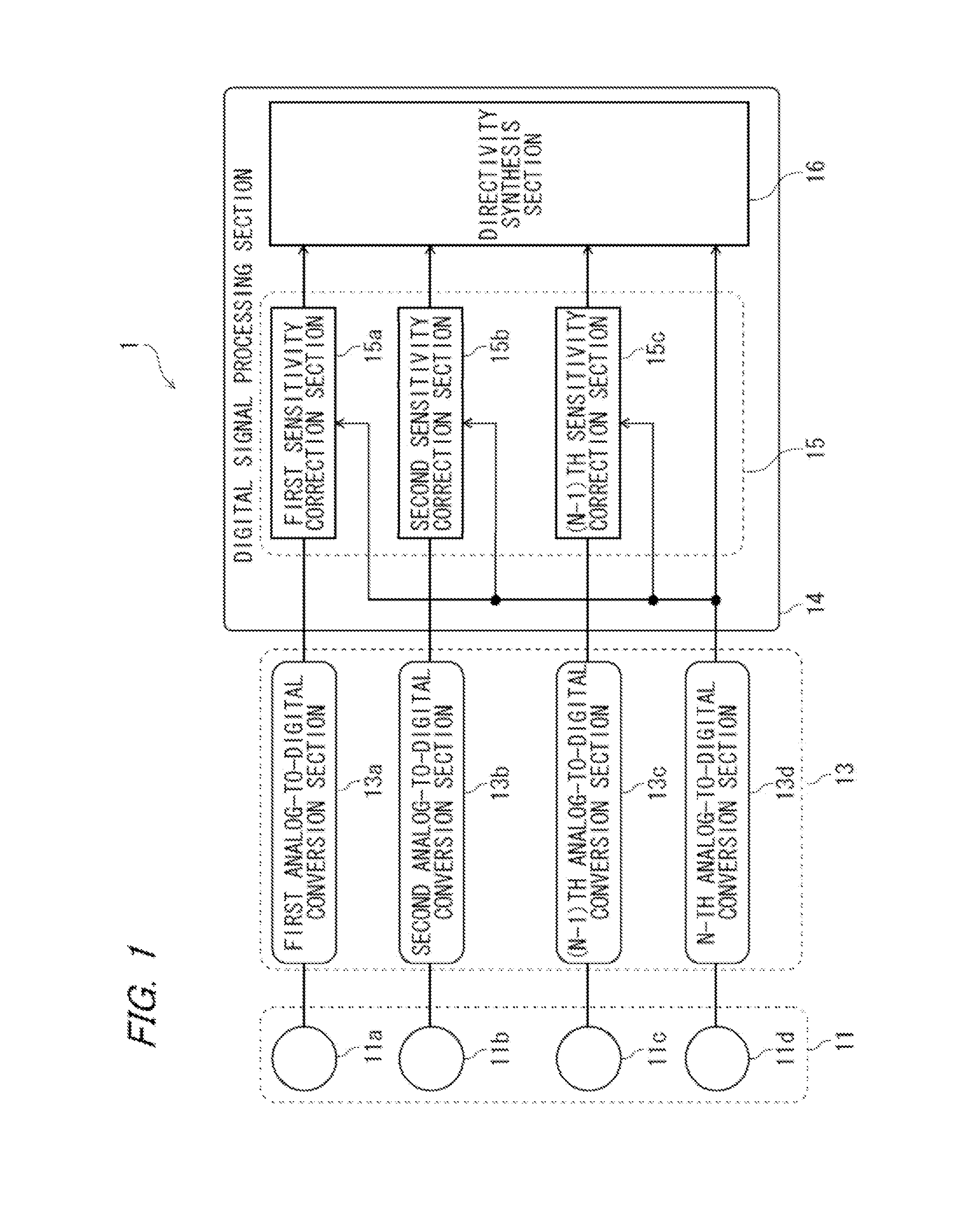
[0027]FIG. 1 is a block diagram showing a structural example of an array microphone device according to a first embodiment of the present invention. An array microphone device 1 shown in FIG. 1 is structured with a microphone array 11, an analog-to-digital conversion section (hereinafter referred to as an A / D conversion section) 13, and a digital signal processing section 14.

[0028]The microphone array 11 is provided with a first microphone unit 11a, a second microphone unit 11b, an (N-1)th microphone unit 11c, and an N-th microphone unit 11d. Each of the microphone units 11a to 11d is aligned in line. In addition, the number of microphone units is not limited to this. Besides, although each of the microphone units 11a to 11d generally has the acoustic characteristic similar to one another, the levels of signals to be output may differ depending on an external environment, duration of use, etc.

[0029]The AD conversion section 13 is provided with a first AD conversion section 13a to wh...

second embodiment

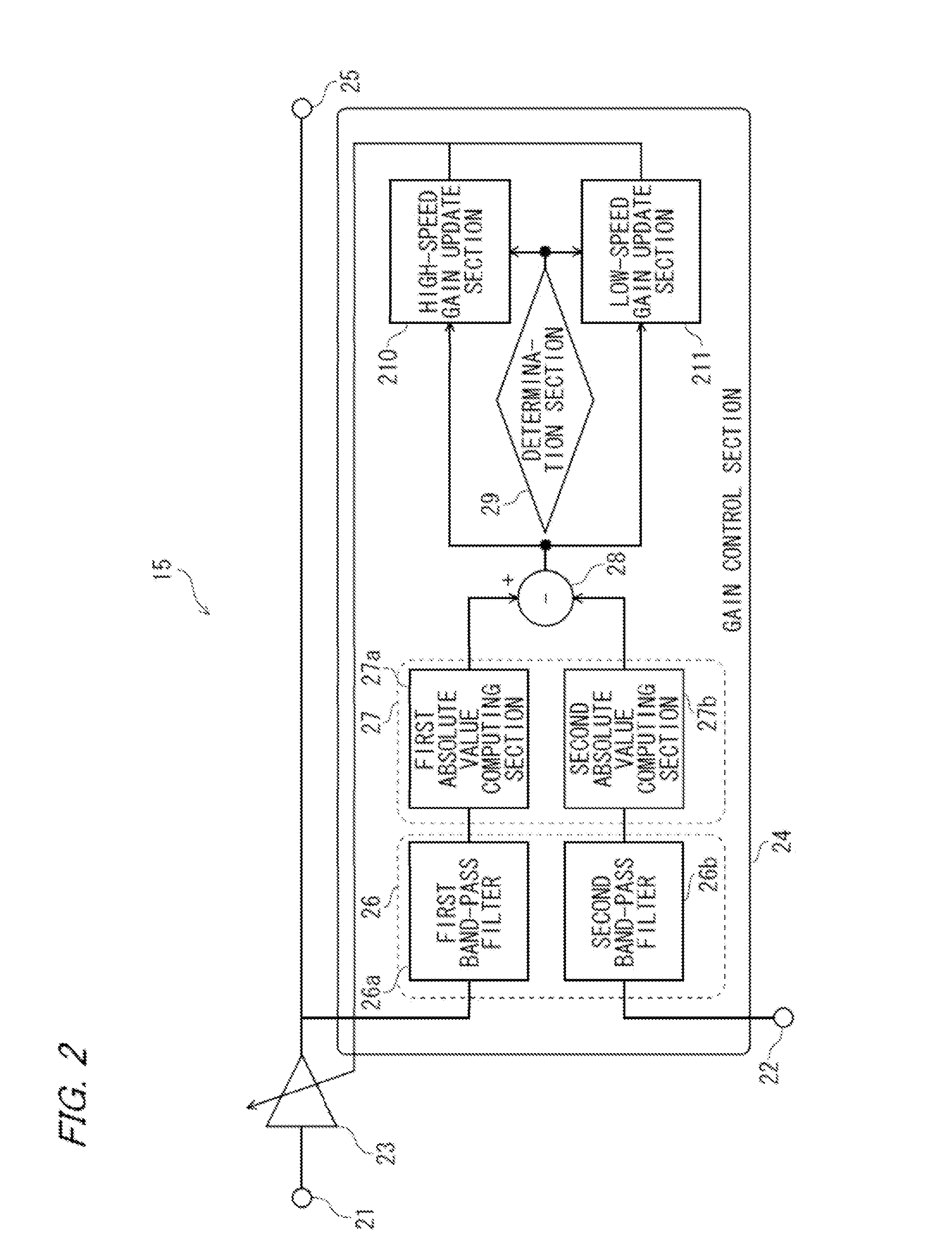
[0076]FIG. 6 is a block diagram showing a structural example of a sensitivity correction section 15B (each of the sensitivity correction sections 15a to 15c) in a second embodiment of the present invention. The structure of the sensitivity correction section 15B shown in FIG. 6 of the present embodiment is basically similar to that of the sensitivity correction section 15 shown in FIG. 2 in the first embodiment. In the sensitivity correction section 15B shown in FIG. 6, same reference numerals are given to components having the same function as those in the sensitivity correction section 15 shown in FIG. 2, and the explanation thereof will be omitted. The difference between FIG. 6 and FIG. 2 is that an output signal 31a from a first absolute value computing section 27a and an output signal 31b from a second absolute value computing section 27b are input to the determination section 29. In addition, the structure other than the sensitivity correction section 15B in the array micropho...


PUM


Abstract

The array microphone device has a microphone array composed of a plurality of microphone units, having a signal input section for inputting a signal from the microphone units to be corrected as a signal to be corrected; a reference signal input section; a gain variable section for making the levels of the signal to be corrected and the reference signal equal; and a gain control section. The gain control section includes a high-speed gain update section for changing the gain with a first amount of change per unit time upon time elapsed since the array microphone device is starting-up being below a predetermined period of time; and a low-speed gain update section for changing the gain with a second amount of change per unit time upon the elapsed time being above the predetermined period of time, the second amount of change being smaller than the first amount of change.

Description

CROSS REFERENCE TO RELATED APPLICATION[0001]This application is a continuation of PCT application No. PCT / JP2011 / 004746, which was files on Aug. 25, 2011 based on Japanese Patent Application (No. 2011-134562) filed on Jun. 16, 2013, the contents of which are incorporated herein by reference. Also, all the references cited herein are incorporated as a whole.BACKGROUND OF THE INVENTION[0002]1. Technical Field[0003]The present invention relates to an array microphone device, and, more specifically, to an array microphone device having a sensitivity correction function.[0004]2. Background Art[0005]An array microphone device has been conventionally known as one of directional microphones. The array microphone device, in which a plurality of microphones is arranged, executes the signal processing on the input sound so as to be able to acquire spatial information of a sound that cannot be obtained by a single microphone. Thereby, the directivity control is applied, and estimation can be ma...

Claims


Application Information

Patent Timeline
IPC IPC(8): H03G3/20H04R3/00
CPCH04R3/005H03G3/20H04R1/406H04R29/006
Inventor YAMADA, KATSUSHI
Owner PANASONIC INTELLECTUAL PROPERTY MANAGEMENT CO LTD
Why Eureka
Try Eureka