Highly airtight gas pump

Active Publication Date: 2014-04-10
TRICORE CORP
View PDF11 Cites 13 Cited by
  • Summary
  • Abstract
  • Description
  • Claims
  • Application Information

AI Technical Summary

Benefits of technology

[0008]In light of the structure indicated above, the hollow retractable portion, the intake valve, and the flexible tube are integrated in one piece, so the whole number

Problems solved by technology

However, in the aforesaid structure, the number of the components of the conventional gas pump are numerous and they are manufactured individually and then put together, so the assembly of those parts becomes a trouble and the parts

Method used


Image

  • Highly airtight gas pump
  • Highly airtight gas pump
  • Highly airtight gas pump

Examples


Example

[0016]A preferred embedment of the present invention is provided in the following paragraphs accompanied with the drawings to describe and illustrate the structure, technical features, and effects of the present invention recited as follows.

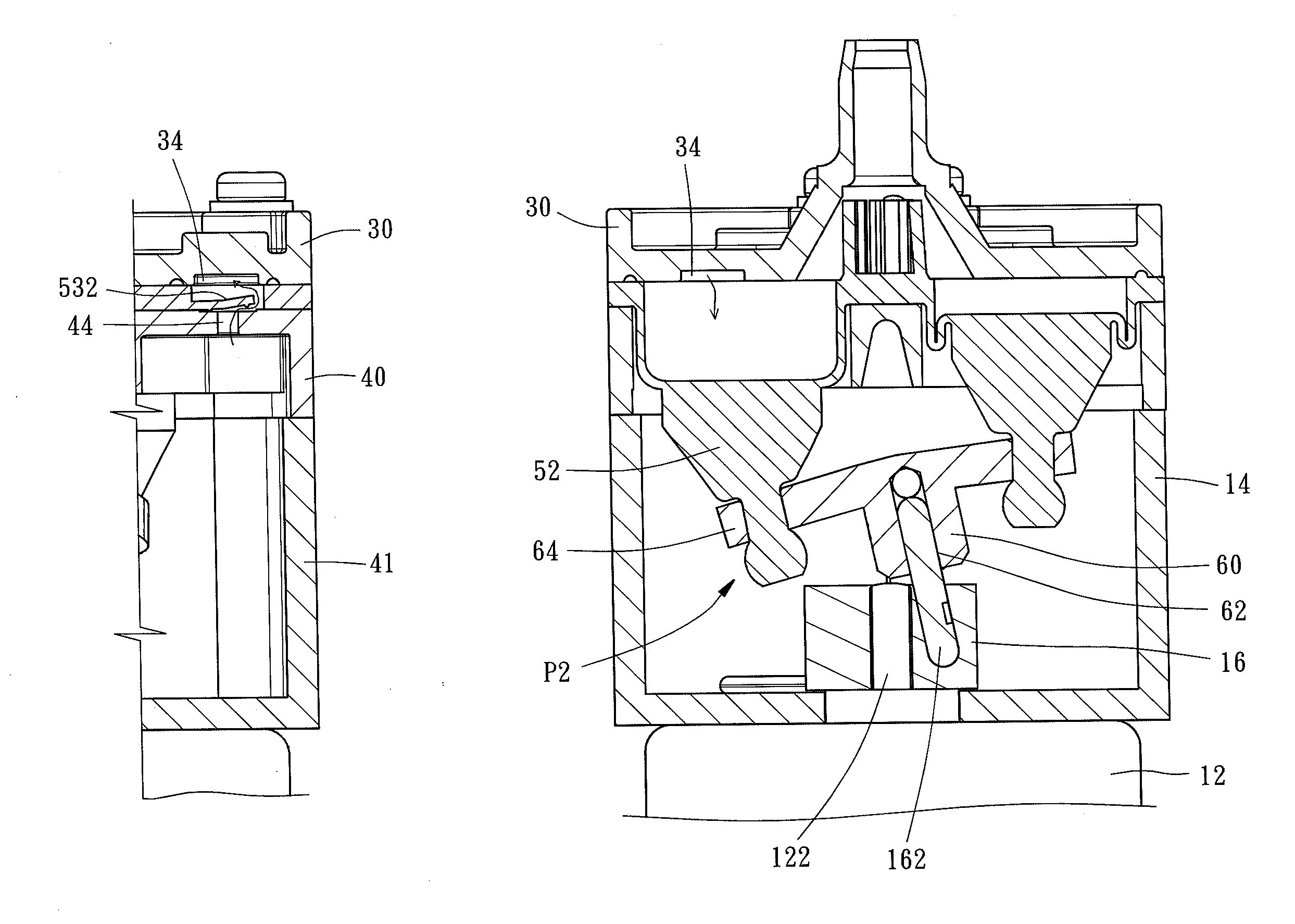
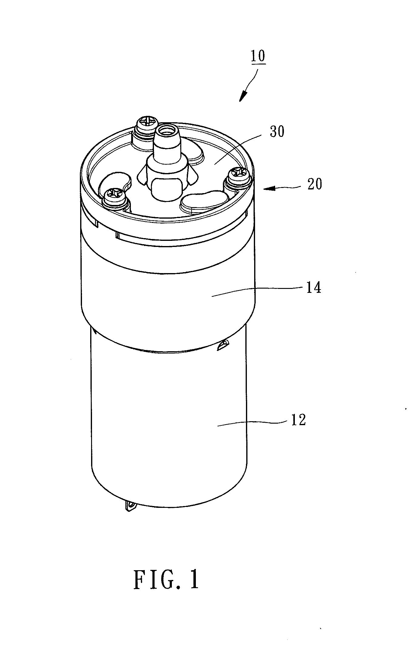
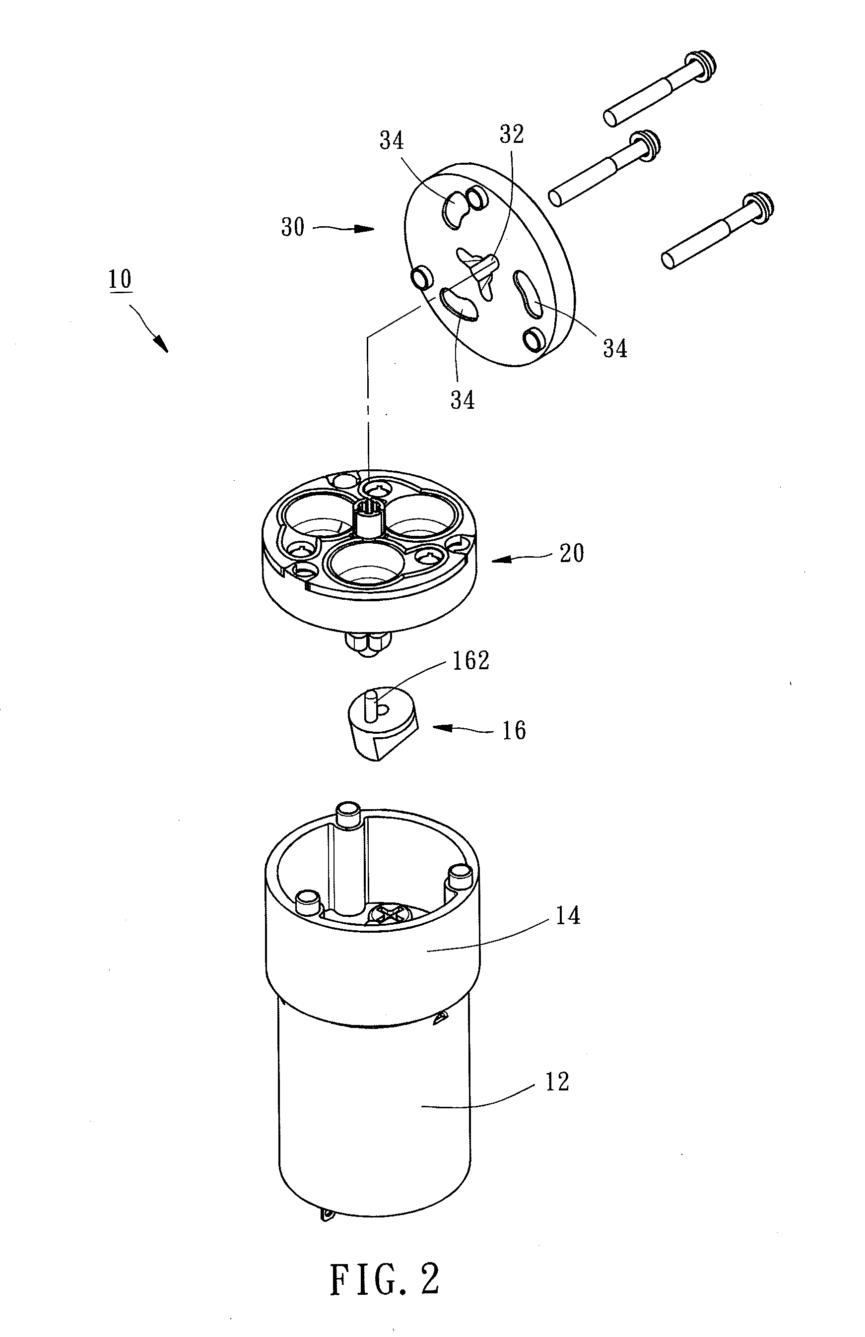
[0017]Referring to FIGS. 1-2, a gas pump 10 constructed according to a preferred embodiment of the present invention can be driven by a motor 12 for gas charging and discharging. The motor 12 is fixed to a motor holder 144 and includes a rotary shaft 12, as shown in FIG. 6B. The rotary shaft 122 is sleeved with a swivel member 16 having an acentric shaft 162 arranged slantingly. The gas pump 10 of the present invention is composed of a gas suction member 20 and a gas exhaust member 30. The detailed descriptions and operations of these elements as well as their interrelation are recited in the respective paragraphs as follows.

[0018]Referring to FIGS. 3-5, the gas suction member 20 is formed of a gasbag holder 40, a gasbag 50, and a pressure contro...


PUM


Abstract

A gas pump is composed of a gas suction member and a gas exhaust member. The gas suction member includes a gasbag having a hollow retractable portion being drivable by a motor for oppression or expansion, an intake valve allowing the air to pass therethrough when the hollow retractable portion is oppressed, and a flexible tube having two crosscuts, by which the flexible tube is divided into two vent valvular pieces. Each of the vent valvular pieces has a reinforcing strip formed on an internal wall thereof for forcing each of the vent valvular pieces to seal the exhaust passage. The gas exhaust member is mounted to the gasbag and includes a venthole and a guide slot. The venthole can receive the flexible tube therein. The guide slot communicates the hollow retractable portion and the intake valve for guiding the air into the hollow retractable portion.

Description

BACKGROUND OF THE INVENTION[0001]1. Field of the Invention[0002]The present invention relates generally to a gas pump and more particularly, to a highly airtight gas pump.[0003]2. Description of the Related Art[0004]A conventional gas pump is composed of an outtake valve, a stopper, a gasbag assembly, a plurality of intake plug, and a control bar, controlling ascent or descent of the control bar via a motor for oppressing and inflating each gasbag of the gasbag assembly. When each gasbag is oppressed, the air is sucked into the gasbag through each inlet. When each gasbag is inflated, the air is expelled out of the gasbag through a valvular piece. In this way, the purposes of air charging and discharging can be reached.[0005]However, in the aforesaid structure, the number of the components of the conventional gas pump are numerous and they are manufactured individually and then put together, so the assembly of those parts becomes a trouble and the parts are subject to malposition the...

Claims


Application Information

Patent Timeline
IPC IPC(8): F04B45/00
CPCF04B45/043F04B45/022F04B45/027F04B45/047F04B1/205F04B39/1033
Inventor YU, CHENG-FANG
Owner TRICORE CORP
Why Eureka
Try Eureka