Cavity wall structure and cavity wall plate of liquefied natural gas cargo tank

A technology for liquefied natural gas and cavity walls, which is applied to the outer walls of container structures, gas processing/storage purposes, and hull panels, etc. Possibility, easy operation, high stability effect

Active Publication Date: 2016-02-17
SAMSUNG HEAVY IND CO LTD
View PDF4 Cites 0 Cited by
  • Summary
  • Abstract
  • Description
  • Claims
  • Application Information

AI Technical Summary

Problems solved by technology

Therefore, there is a high probability that the existing flexible triple plate 7 cannot perform the liquid-tight and / or air-tight function as the secondary chamber wall

Method used


Image

  • Cavity wall structure and cavity wall plate of liquefied natural gas cargo tank
  • Cavity wall structure and cavity wall plate of liquefied natural gas cargo tank
  • Cavity wall structure and cavity wall plate of liquefied natural gas cargo tank

Examples


Embodiment Construction

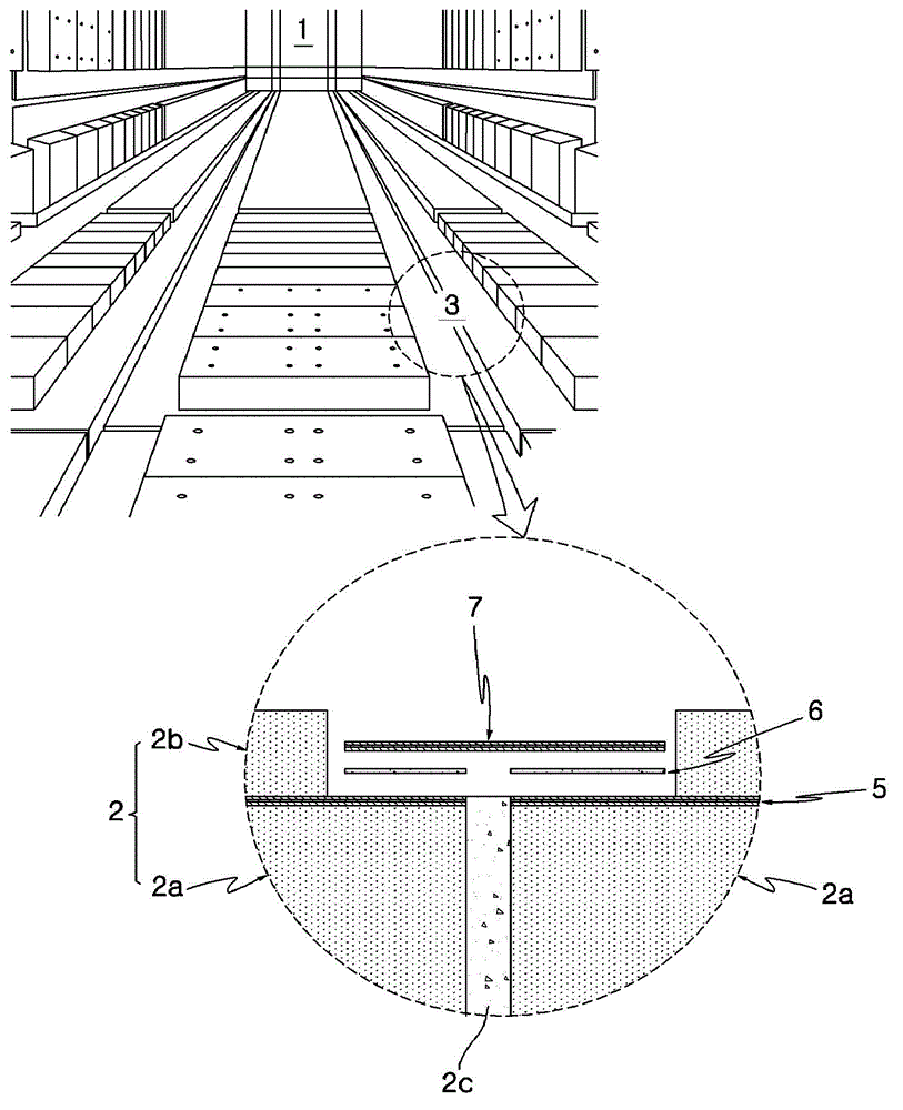
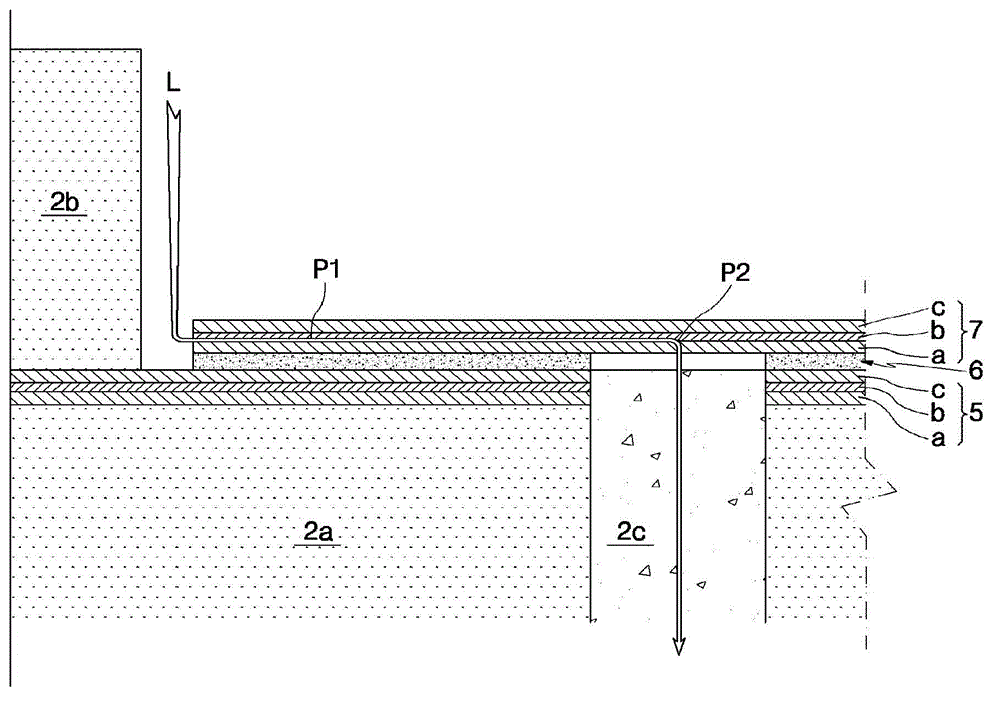
[0033] Below, refer to Figure 2 to Figure 4 , the cavity wall plate and cavity wall structure of the liquefied natural gas cargo tank according to the embodiment of the present invention will be described in detail. Throughout the drawings, the same or similar reference numerals represent the same or similar constituent elements.

[0034] The following specific examples are only used to illustrate the chamber wall plate and chamber wall structure of the LNG cargo tank according to the present invention, and are not intended to limit the scope of the present invention.

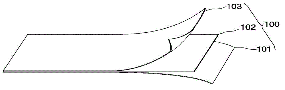
[0035] figure 2 It is a structural diagram of the cavity wall plate used in the cavity wall structure of the liquefied natural gas cargo tank according to an embodiment of the present invention.

[0036] like figure 2 As shown, for the secondary cavity wall of the LNG cargo tank, the cavity wall plate 100 of the LNG cargo tank according to an embodiment of the present invention can be made into a sandwich s...


PUM

PropertyMeasurementUnit
thicknessaaaaaaaaaa
thicknessaaaaaaaaaa
thicknessaaaaaaaaaa

Abstract

The liquefied natural gas cargo tank cavity panel includes a first cavity wall panel and a second cavity wall panel laminated for a secondary cavity wall of an liquefied natural gas cargo tank, each cavity wall panel comprising: a first metal layer; a second metal layer; and glass A fiber layer is arranged between the first metal layer and the second metal layer and integrated by bonding.

Description

technical field [0001] The present invention relates to a cavity wall structure of a liquefied natural gas cargo tank of a liquefied natural gas carrier or a floating offshore structure producing and storing liquefied natural gas, in particular to a cavity wall structure of a liquefied natural gas cargo tank and a cavity used for the cavity wall structure Wall panels. Background technique [0002] Generally, liquefied natural gas (LNG) refers to a colorless and transparent ultra-low temperature liquid that is cooled to about -163°C to reduce its volume by 1 / 600 of natural gas mainly composed of methane. [0003] A LNG carrier that transports the above-mentioned LNG or a floating offshore structure that produces and stores LNG has a cargo tank capable of storing and storing LNG liquefied in an ultra-low temperature state. In the LNG cargo tank described above, a membrane is used as the primary chamber wall and a triplex is used as the secondary chamber wall. Among them, the...

Claims


Application Information

Patent Timeline
Patent Type & Authority Patents(China)
IPC IPC(8): B63B25/16F17C1/12B65D90/06B63B3/68
CPCB63B3/68B63B25/16F17C3/027F17C2201/0157F17C2201/052F17C2203/0602F17C2203/0631F17C2203/0643F17C2203/0646F17C2221/033F17C2223/0161F17C2223/033F17C2260/036F17C2270/0105B32B15/14B32B17/061B32B2250/03F17C2203/0358F17C2203/0636F17C2203/0663F17C2270/0107B65D90/08F17C13/001B65D90/06
Inventor 方昌先金志韩李锺圭
Owner SAMSUNG HEAVY IND CO LTD
Why Eureka
Try Eureka