Jaw assemblies for electrosurgical instruments and methods of manufacturing jaw assemblies

a technology of electrosurgical instruments and jaw assemblies, applied in the field of electrosurgical instruments, can solve the problems of time-consuming and expensive processes, and achieve the effects of reducing or eliminating complex machining operations, reducing or eliminating cost, and effective manufacturing

Active Publication Date: 2014-04-10
TYCO HEALTHCARE GRP LP
View PDF8 Cites 53 Cited by
  • Summary
  • Abstract
  • Description
  • Claims
  • Application Information

AI Technical Summary

Benefits of technology

[0010]A continuing need exists for tightly-toleranced jaw assembly components that can be readily integrated into manufacturing assembly processes for the production of end-effector assemblies for use in electrosurgical instruments, such as electrosurgical forceps. Further need exists for the development of a manufacturing process that effectively fabricates jaw assembly components at low cost, and results in the formation of a reliable electrosurgical instrument that meets specific tolerance requirements for proper jaw alignment and other tightly-toleranced jaw assembly features, with reduction or elimination of complex machining operations.
[0011]A continuing need exists for a reliable electrosurgical instrument that regulates the gap distance between opposing jaw assemblies, reduces the chances of short circuiting the opposing jaws during activation, and assists in gripping, manipulating and holding tissue prior to and during activation and dividing of the tissue. A continuing need exists for improved thermal resistance, strength and rigidity of jaw assemblies using lower cost technologies.

Problems solved by technology

Jaw assembly components of end-effector assemblies for use in electrosurgical instruments are required to meet specific tolerance requirements for proper jaw alignment and other closely-toleranced features, and are generally manufactured by expensive and time-consuming processes that typically involve complex machining operations.

Method used


Image

  • Jaw assemblies for electrosurgical instruments and methods of manufacturing jaw assemblies
  • Jaw assemblies for electrosurgical instruments and methods of manufacturing jaw assemblies
  • Jaw assemblies for electrosurgical instruments and methods of manufacturing jaw assemblies

Examples


Embodiment Construction

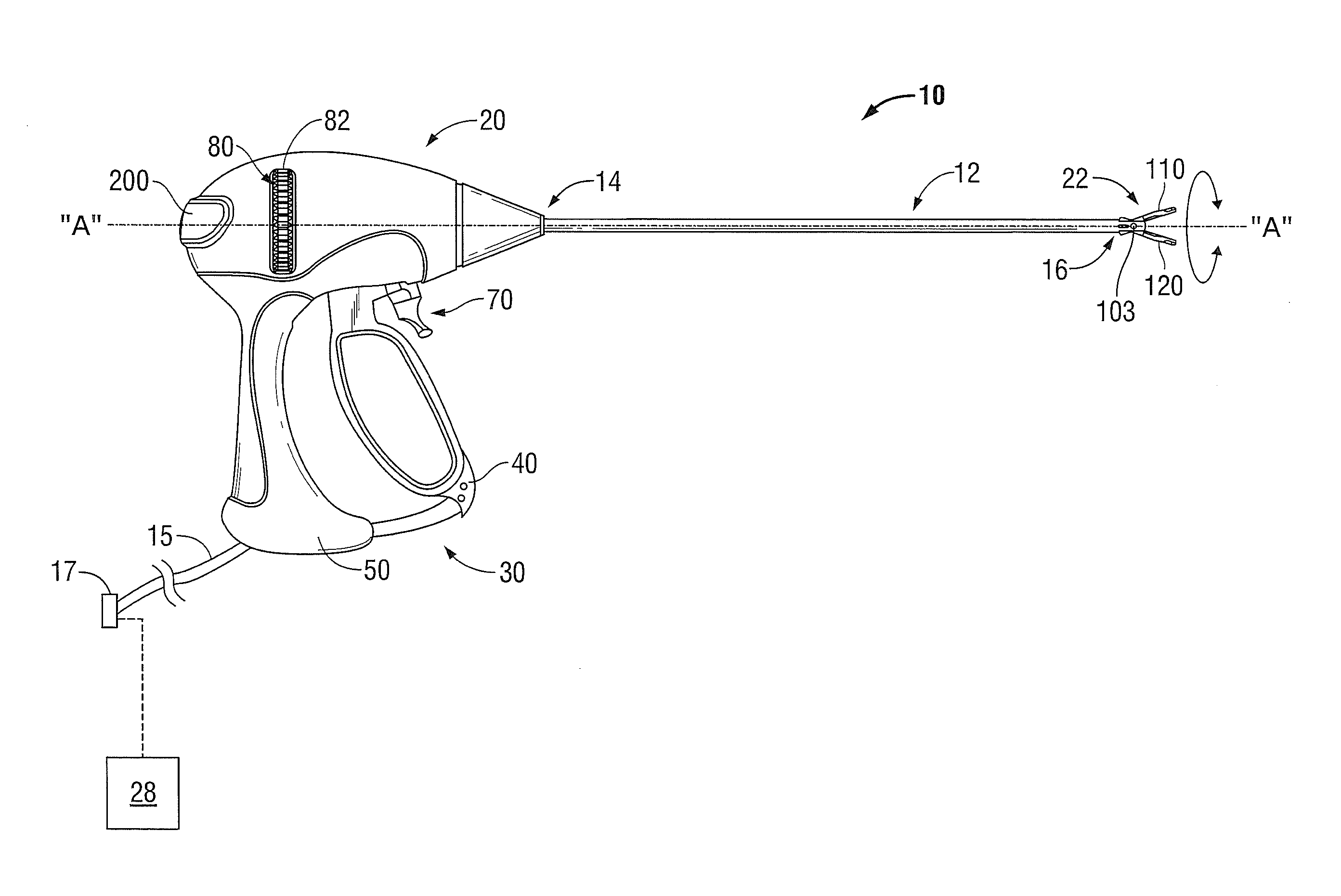
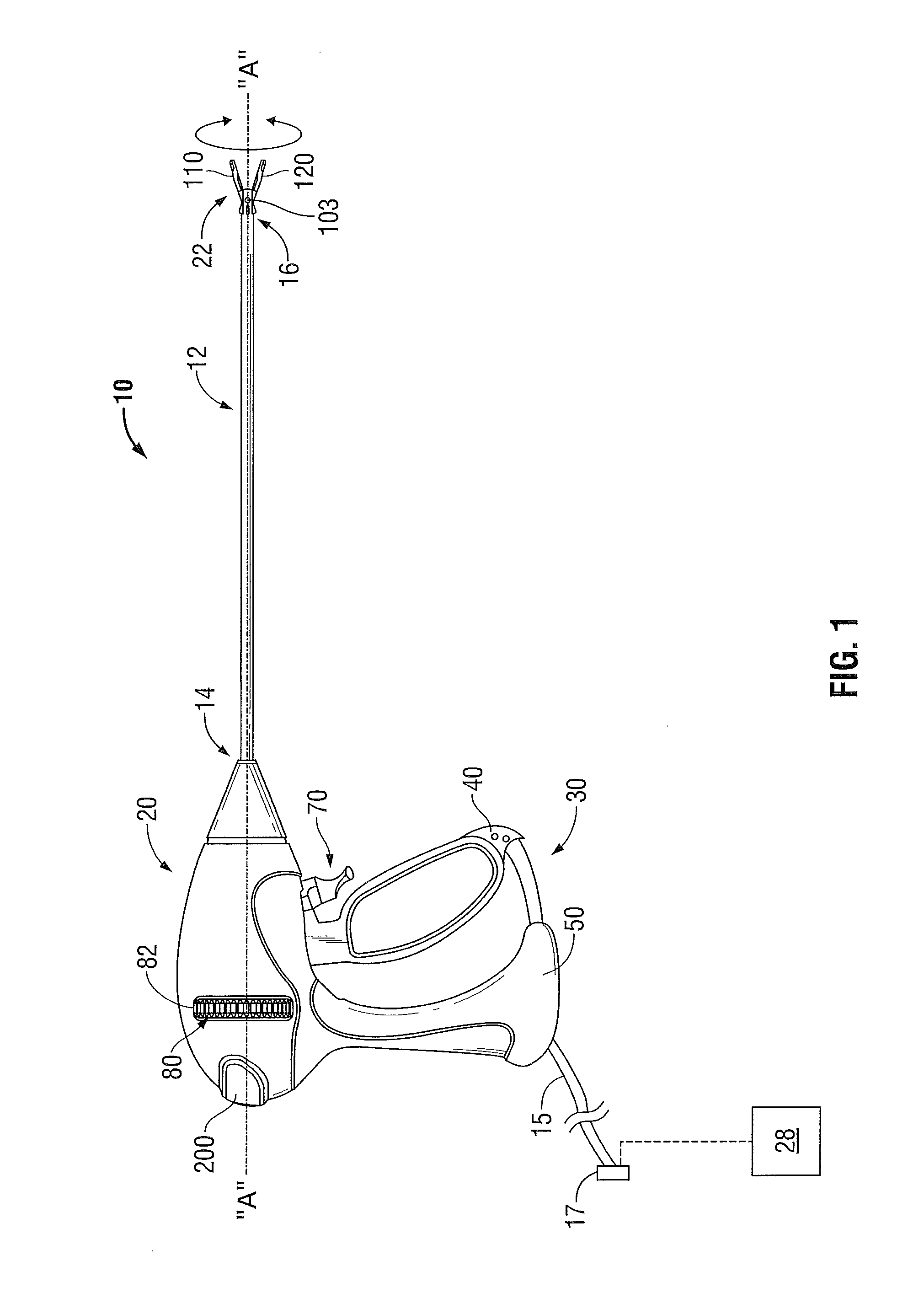
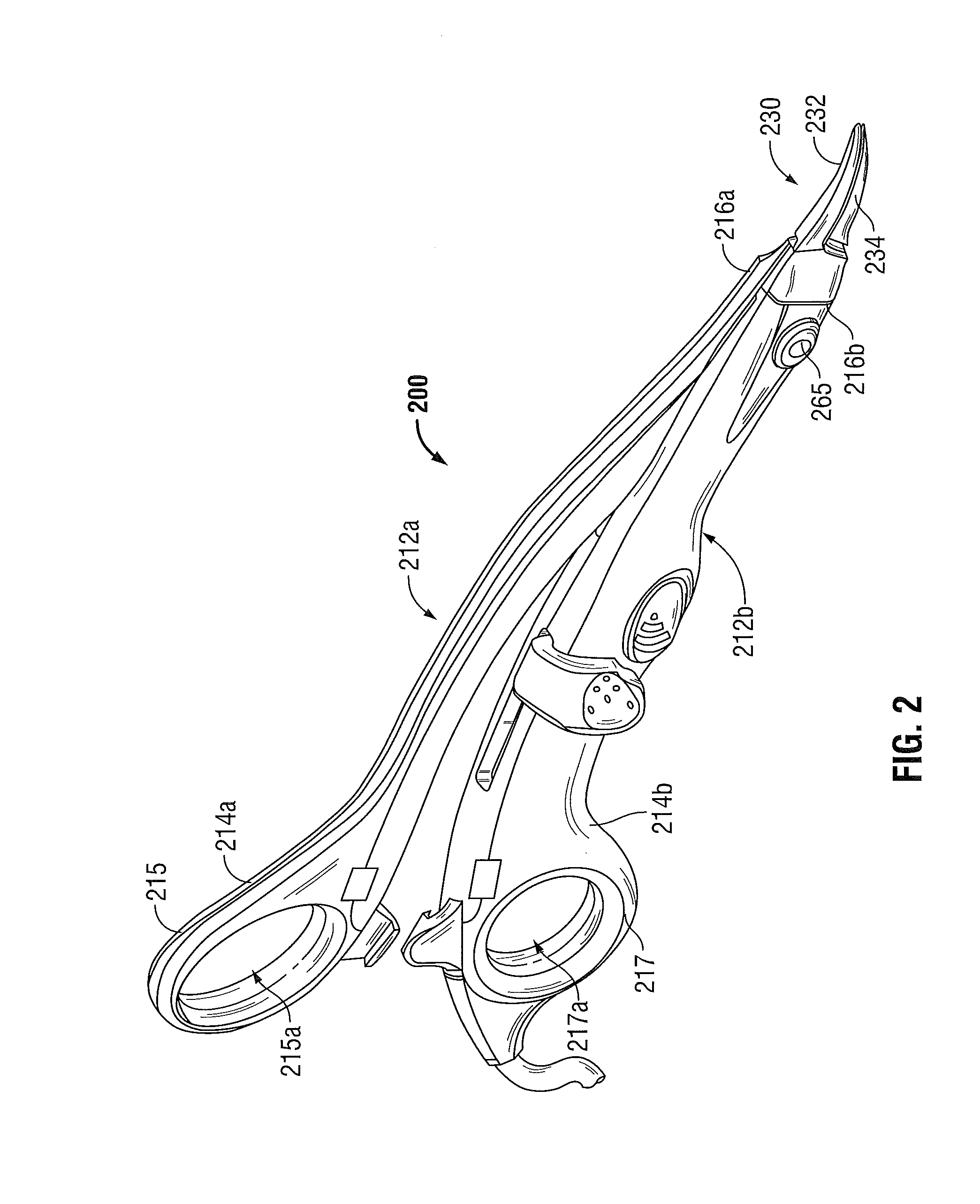
[0043]Hereinafter, embodiments of jaw assemblies for use in electrosurgical instruments and methods of manufacturing jaw assemblies of the present disclosure are described with reference to the accompanying drawings. Like reference numerals may refer to similar or identical elements throughout the description of the figures. As shown in the drawings and as used in this description, and as is traditional when referring to relative positioning on an object, the term “proximal” refers to that portion of the apparatus, or component thereof, closer to the user and the term “distal” refers to that portion of the apparatus, or component thereof, farther from the user.

[0044]This description may use the phrases “in an embodiment,”“in embodiments,”“in some embodiments,” or “in other embodiments,” which may each refer to one or more of the same or different embodiments in accordance with the present disclosure.

[0045]Various embodiments of the present disclosure provide electrosurgical instrume...


PUM

PropertyMeasurementUnit
lengthaaaaaaaaaa
electrically-conductiveaaaaaaaaaa
lengthaaaaaaaaaa

Abstract

A jaw assembly includes an electrically-conductive tissue-engaging structure, a jaw member including a support base, and a non-electrically conductive member including a first portion configured to engage the electrically-conductive tissue-engaging structure and a second portion configured to engage the support base of the jaw member. The non-electrically conductive member adapted to electrically isolate the electrically-conductive tissue-engaging structure from the jaw member. The electrically-conductive tissue-engaging structure and the non-electrically conductive member cooperatively define a longitudinally-oriented knife channel therethrough.

Description

CROSS REFERENCE TO RELATED APPLICATION[0001]The present application claims the benefit of and priority to U.S. Provisional Application Ser. No. 61 / 711,075, filed on Oct. 8, 2012, the entire contents of which are incorporated herein by reference.BACKGROUND[0002]1. Technical Field[0003]The present disclosure relates to electrosurgical instruments. More particularly, the present disclosure relates to jaw assemblies for use in electrosurgical instruments and methods of manufacturing jaw assemblies.[0004]2. Discussion of Related Art[0005]Electrosurgical instruments have become widely used by surgeons. Electrosurgery involves the application of thermal and / or electrical energy to cut, dissect, ablate, coagulate, cauterize, seal or otherwise treat biological tissue during a surgical procedure. Electrosurgery is typically performed using an electrosurgical generator operable to output energy and a handpiece including a surgical instrument (e.g., end effector) adapted to transmit energy to a...

Claims


Application Information

Patent Timeline
Patent Type & Authority Applications(United States)
IPC IPC(8): A61B18/08
CPCA61B18/085A61B18/1445A61B2018/00083A61B2018/00589A61B2018/00595A61B2018/00601A61B2018/0063A61B2018/1457Y10T29/49826A61B2017/2936B23K3/087A61B2017/00526B23P15/00A61B2018/00077A61B2017/2939
Inventor GARRISON, DAVID M.
Owner TYCO HEALTHCARE GRP LP
Why Eureka
Try Eureka