
Structural Support Scheme for the Replacement of Trailing Portions of Sails

a structure support and trailing portion technology, applied in the field of sails, can solve the problems of drag created by the structure of the sail itsel

Inactive Publication Date: 2014-04-17
GEFTER MALCOLM L
View PDF5 Cites 2 Cited by
  • Summary
  • Abstract
  • Description
  • Claims
  • Application Information

AI Technical Summary

Benefits of technology

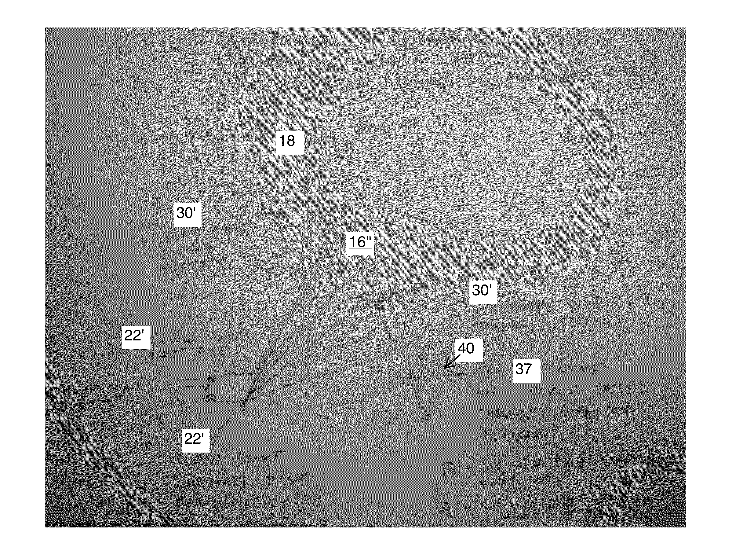
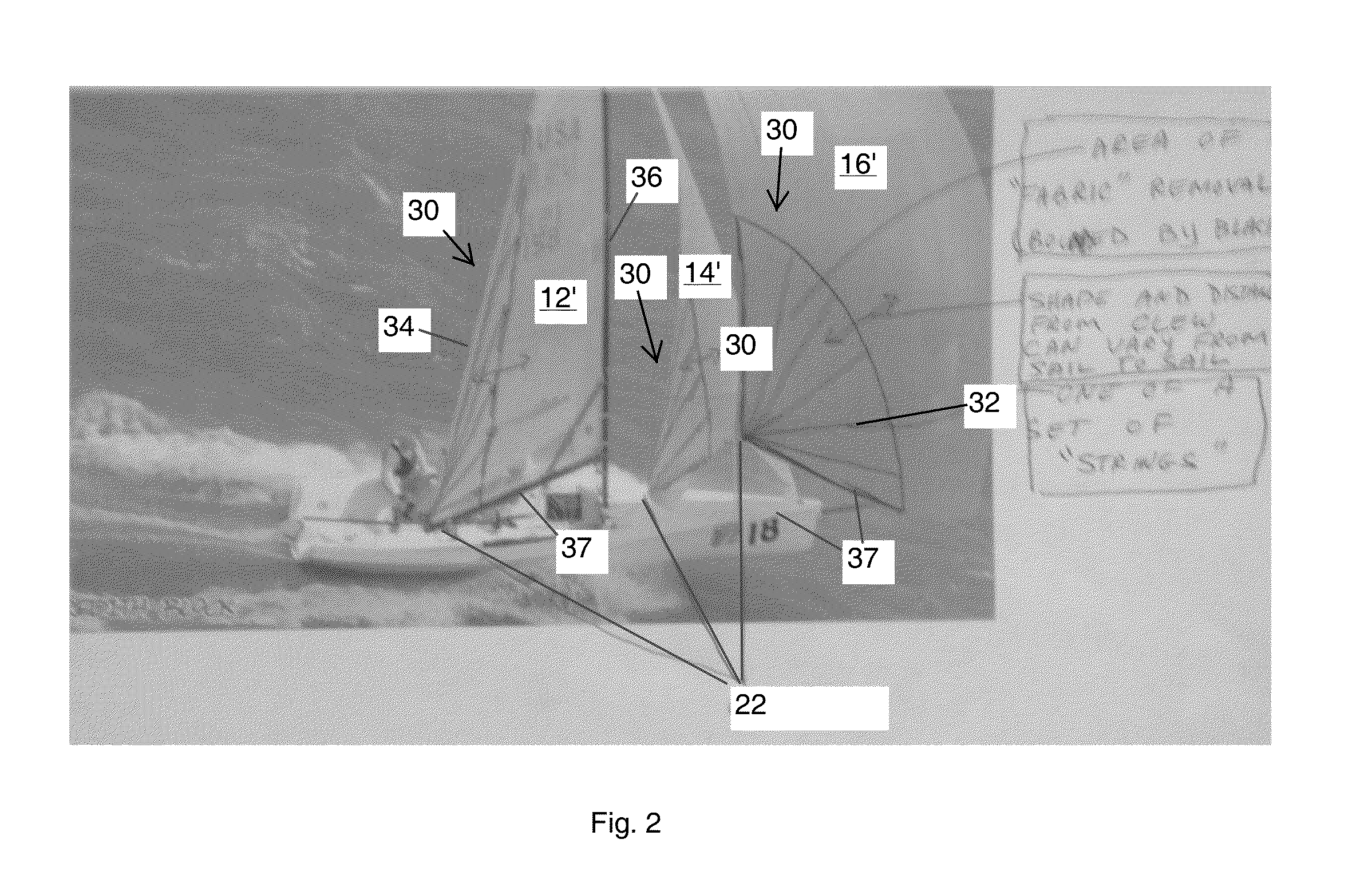
The patent describes a sail for a wind-powered craft that includes a web that flies in the wind. This web has a combination of wind-impermeable and wind-permeable portions that are located between the leading and trailing edges. The ratio of wind-permeable area to wind-impermeable area is between 5 and 80 percent. The sail can also have additional wind-permeable portions in the form of widely spaced strings or lines. The asymmetrical or symmetrical feature of the sail allows for interchangeability between the tack and clew portions of the craft. The method of configuring the sail involves configuring a wind-flying shaped web with a combination of wind-impermeable and wind-permeable portions. The technical effect of this invention is the improved efficiency and performance of wind-powered crafts by utilizing a specialized sail design that maximizes the amount of wind energy captured and reduces the amount of wind energy lost during the process.

Problems solved by technology

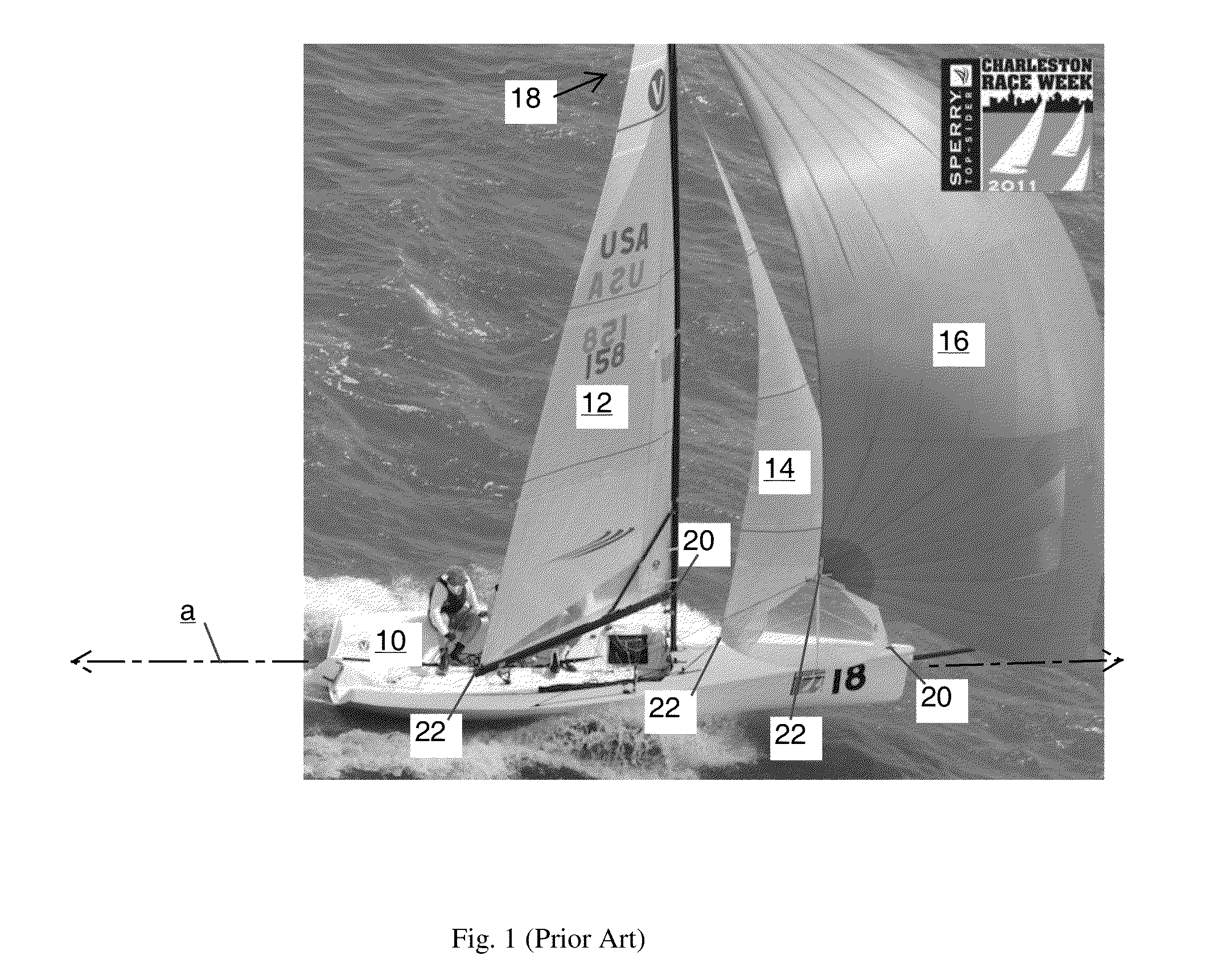
The structure of the sail itself creates drag as it moves through the air, which tends to resist the forward motion of the craft.

Method used


Image

  • Structural Support Scheme for the Replacement of Trailing Portions of Sails
  • Structural Support Scheme for the Replacement of Trailing Portions of Sails
  • Structural Support Scheme for the Replacement of Trailing Portions of Sails

Examples


Embodiment Construction

[0015]In the following detailed description, reference is made to the accompanying drawings that form a part hereof, and in which is shown by way of illustration, specific aspects in which the invention may be practiced. These aspects are described in sufficient detail to enable those skilled in the art to practice the invention, and it is to be understood that other aspects may be utilized. It is also to be understood that structural, procedural and system changes may be made without departing from the spirit and scope of the present invention. In addition, well-known structures, circuits and techniques have not been shown in detail in order not to obscure the understanding of this description. The following detailed description is, therefore, not to be taken in a limiting sense, and the scope of the present invention is defined by the appended claims and their equivalents.

[0016]Where used in this disclosure, the term “axial” when used in connection with an element described herein...


PUM


Abstract

A sail for a wind-powered craft includes a web which forms a flying shape upon engagement with the wind, flying shape extending from leading to trailing edges. The web includes a combination of wind-impermeable and wind-permeable portions disposed between the leading and trailing edges, with a permeability ratio of wind-permeable area to wind-impermeable area within a range of about 5 to 80 percent.

Description

RELATED APPLICATION[0001]This application claims the benefit of U.S. Provisional Patent Application Ser. Nos. 61 / 712,458, entitled Structural Support Scheme for the Replacement of the Clew Section of Sails, filed on Oct. 11, 2012, and 61 / 721,054, entitled A Structural Support Scheme for the Replacement of the Clew Section of Sails, filed on Nov. 1, 2012, the contents, both of which, are incorporated herein by reference in their entireties for all purposes.BACKGROUND[0002]1. Technical Field[0003]This invention relates to a sail configured to fly in its working shape while being lighter and having less drag relative to its lift characteristics, than conventional sails. In spinnaker and jib embodiments, the sail may have a better ratio of lift to heeling moment, and allow tighter sheeting angles with less backwinding of the mainsail, respectively.[0004]2. Background Information[0005]Sails used on sailboats (and on wind powered craft in general) propel the boat in substantially all poin...

Claims


Application Information

Patent Timeline
Patent Type & Authority Applications(United States)
IPC IPC(8): B63H9/06
CPCB63H9/0657B63B2231/40B64D17/12B63H9/067
Inventor GEFTER, MALCOLM L.
Owner GEFTER MALCOLM L
Learn More