

Control of blowdown in steam boilers
a technology of steam boilers and control valves, which is applied in the field of steam boilers, can solve problems such as blowdown operation, and achieve the effect of reducing heat loss
- Summary
- Abstract
- Description
- Claims
- Application Information
AI Technical Summary
Benefits of technology
Problems solved by technology
Method used
Image

Examples
Embodiment Construction
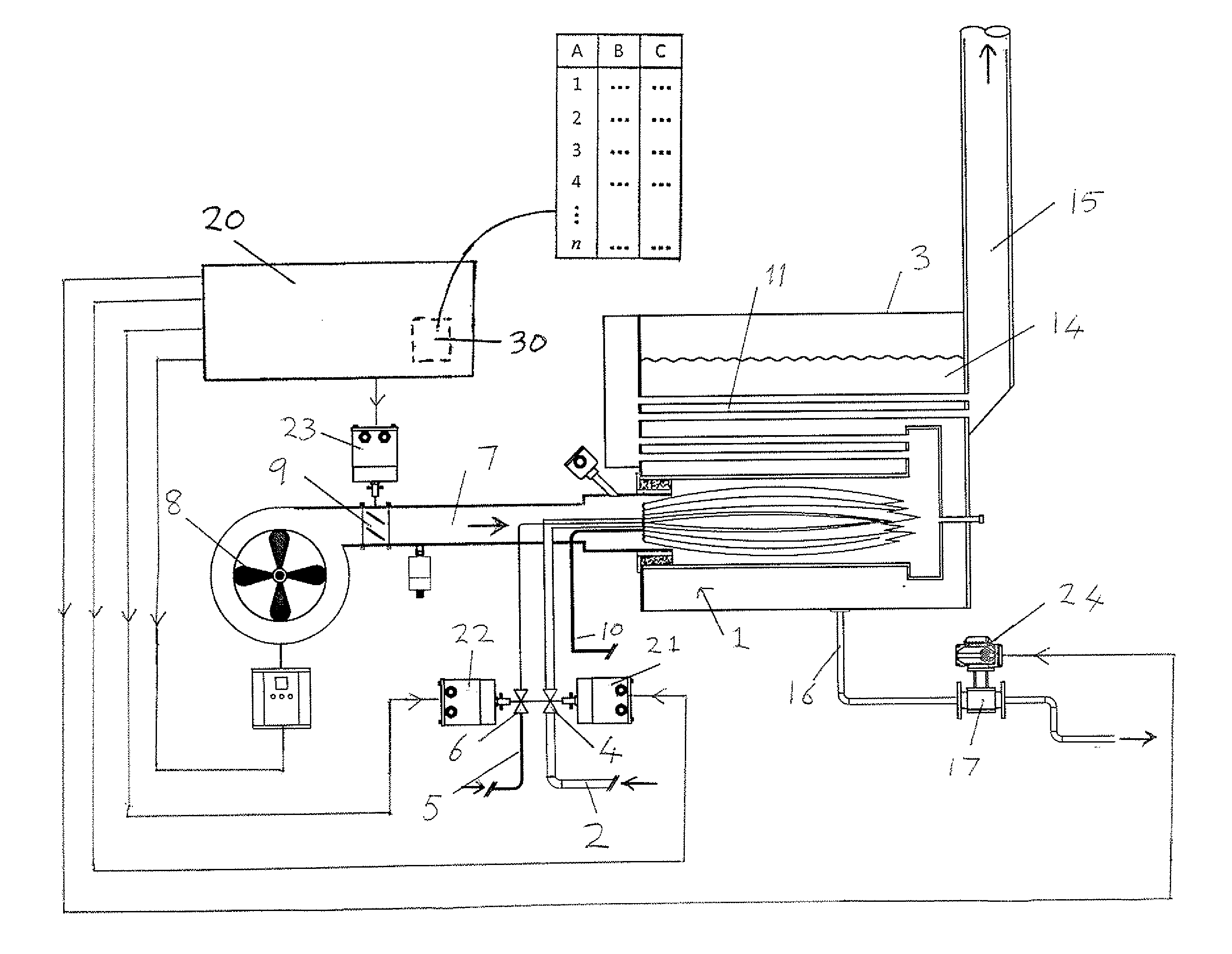
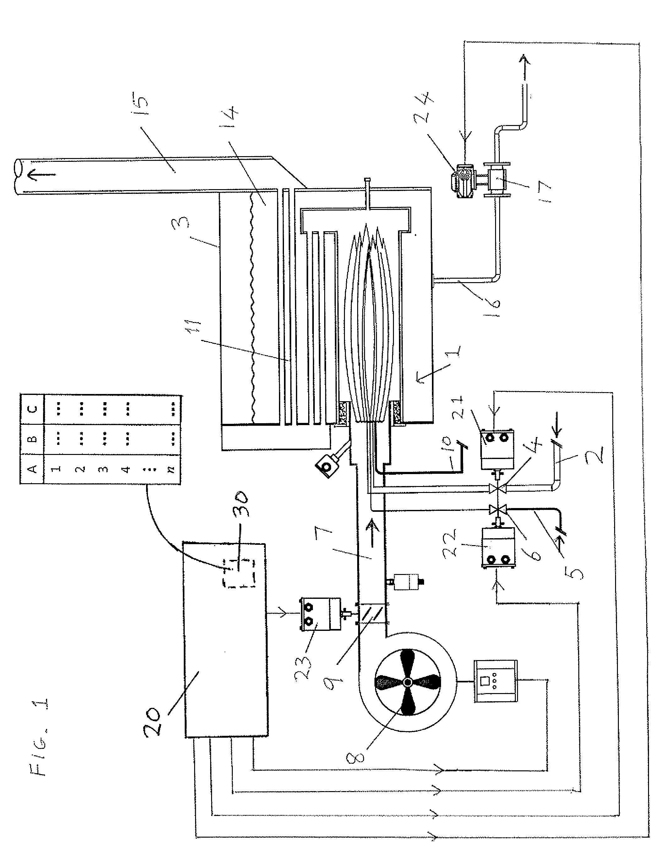
[0025]Referring to FIG. 1, a pressurised steam boiler installation generally comprises a fuel burner 1, which in this case is a gas and oil burner, and a boiler housing 3. Gas is fed along a pipe 2 via a butterfly valve 4, and / or oil is fed along a pipe 5 via a butterfly valve 6. Air is driven along a duct 7 by a fan 8 via a damper valve 9. The burner also has a pilot fuel feed 10.
[0026]In the burner 1, the fuel and air are mixed and combustion takes place. The products of combustion pass from the burner 1 through a heat exchanger 11 in the boiler housing 3 containing water 14 into the bottom of a stack 15. The combustion products pass up the stack 15 and into the atmosphere.
[0027]An outlet pipe 16 extends from the bottom of the boiler housing 3 via a blowdown flow control valve 17 to a blowdown receiver (not shown), providing a bottom blowdown facility that is in most respects conventional, but employs an electrically controlled blowdown valve and servomotor assembly. The use of an...
PUM
 Abstract
Description
Claims
Application Information