Non-coring reduced shearing needle

a shearing needle and non-coring technology, applied in the field of needle designs, can solve the problems of material against material can fall into the side hole or can be planed, and increase the risk, so as to increase the outer diameter of the needle, increase the compression of the traversed material, and the effect of the greatest resistance to flow

Inactive Publication Date: 2014-04-17
CORAVIN
View PDF4 Cites 22 Cited by
  • Summary
  • Abstract
  • Description
  • Claims
  • Application Information

AI Technical Summary

Benefits of technology

[0005]In single lumen needles, the smallest flow area is generally defined by the inner diameter of the needle. However, in the case of a closed tip needle employing a side hole, the side hole itself is generally the minimum flow area or otherwise provides the greatest resistance to flow. This is because as the area of the side hole increases, there is an increasing risk that material can fall into the side hole, or can be planed, sheared, cut or cored by the edges of the side hole as the needle progresses through the material. This is particularly true if the material being traversed is under compression or constrained against expansion, as is often the case with a wine bottle cork. In such cases, dilation of the material by the closed needle tip results in compression of the material against the outer diameter of the needle. This compression is partially relieved as the material passes over the needle side hole by expansion of the material toward the inner diameter of the needle, putting this material at risk of being cut, cleaved, sheared, planed or laterally cored when it contacts the advancing edge of the side hole. This shearing risk scales with side hole area as well as increasing outer diameter of the needle. Increasing side hole area provides more room for expansion of the compressed material toward the inner bore of the needle, and larger needle diameters increase the compression of the traversed material against the outer surface of the needle, hence increasing the propensity for the material to expand into the side hole. Coring, cleaving, planing, or shearing off of material can occur both on insertion and removal of the needle, as both the leading and trailing edges of the side hole may engage material the edge is advanced through the material. To prevent or reduce such coring risk, needle side holes may be made less than the cross-sectional flow area of the needle bore, creating an unwanted flow restriction but avoiding unwanted blockage of the needle side holes by sheared off cork or other material.
[0006]Aspects of the invention provide for maximized or otherwise enhanced flow through closed-tip needles having one or more side holes while limiting the coring, cleaving, planing, or shearing off of the material being traversed by the side holes. By limiting shearing of material by the needle side hole(s), damage to the material may be reduced and clogging of, or the collection of debris within, the needle bore can avoided. In some embodiments, edges of the side holes may be deflected inwardly away from the outer surface of the needle or tapered inwardly, either around the entire circumference of the side hole, or at least at those regions of the edge that are transverse to the direction of needle insertion and / or removal. In other embodiments, edges of the side holes may be deflected outwardly away from the outer surface of the needle, e.g., by building up the edge of the hole away from the outer surface of the needle or deflecting the edges outwardly away from the needle center. Other techniques for reducing material shearing disclosed herein include shaping and positioning the side holes relative to the tangency of the needle body and tip, and sizing the side holes with respect to the needle bore dimensions. In some embodiments, a needle side hole can be shaped such that its leading and trailing edge possess a convex profile in two dimensions and tapered edges. Also, the leading and trailing edge of the side hole may be joined by two parallel edges.

Problems solved by technology

This is because as the area of the side hole increases, there is an increasing risk that material can fall into the side hole, or can be planed, sheared, cut or cored by the edges of the side hole as the needle progresses through the material.
In such cases, dilation of the material by the closed needle tip results in compression of the material against the outer diameter of the needle.
This compression is partially relieved as the material passes over the needle side hole by expansion of the material toward the inner diameter of the needle, putting this material at risk of being cut, cleaved, sheared, planed or laterally cored when it contacts the advancing edge of the side hole.

Method used


Image

  • Non-coring reduced shearing needle
  • Non-coring reduced shearing needle
  • Non-coring reduced shearing needle

Examples


Embodiment Construction

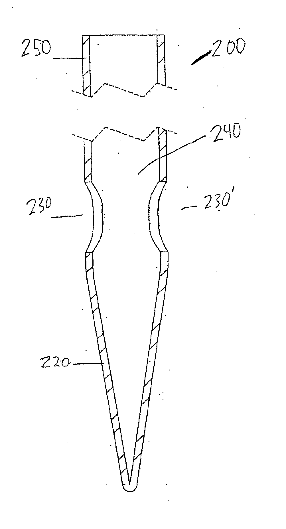
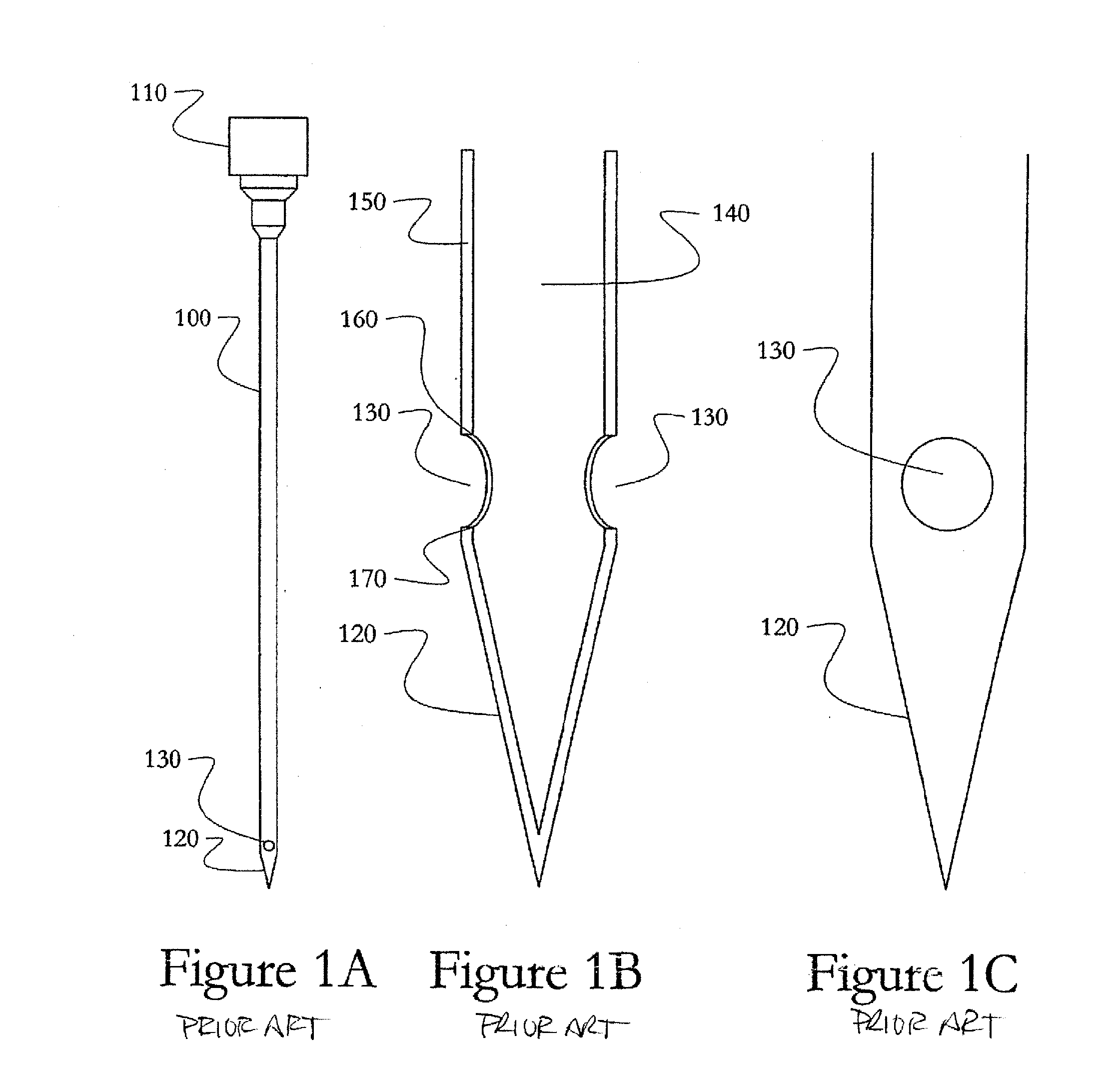
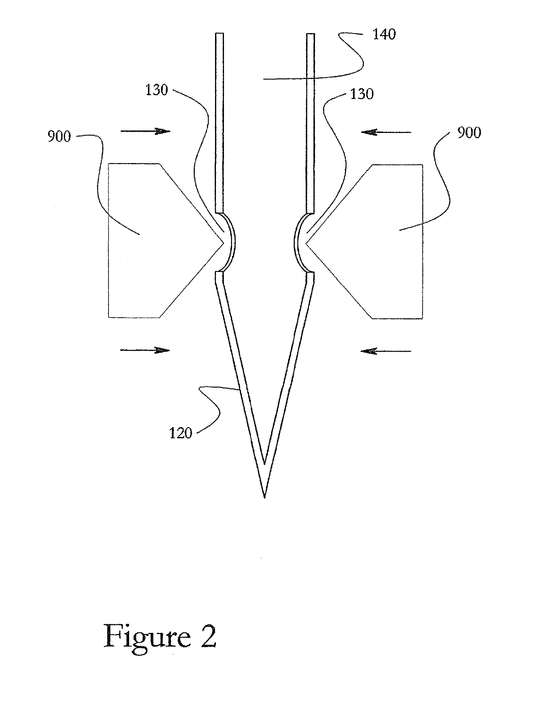
[0026]Often, the smallest flow area in standard needle cannulae is defined by the inner diameter of the needle. However, in the case of a closed tip needles employing a side hole, the side hole itself generally defines the minimum flow area. This is because as the area of the side hole increases, there is an increasing risk that material can fall into the side hole and be planed, sheared, cut or cored by the edges of the side hole as the needle progresses through the material. This is particularly true if the material being traversed is under compression or constrained against expansion.

[0027]One or more aspects of the present invention relates to methods and devices to maximize flow rate through non-coring needles while minimizing the risk of cleaving, cutting or shearing the material being traversed. More specifically, one or more aspects of the present invention relate to methods of modifying the geometry of the edges of side holes in a non-coring needle to maximize flow area whi...


PUM


Abstract

Method and apparatus for beverage extraction needle side holes or apertures. The leading and trailing edges of the apertures may be shaped or otherwise configured to help reduce the possibility of coring or shearing of material as the needle is inserted into and/or withdrawn from material, such as a cork. Convex leading and/or trailing edges may help deflect material away from the aperture, reducing shearing. Concave leading and/or trailing edges may help prevent entry of material into the aperture, again reducing shearing.

Description

[0001]This application claims the benefit under 35 U.S.C. §119(e) of U.S. provisional application No. 61 / 795,225, filed Oct. 12, 2012, which is incorporated by reference herein in its entirety.FIELD OF THE INVENTION[0002]This invention relates to needle designs, e.g., for needles adapted to penetrate a corked vessel such as a bottle of wine for accessing its contents.BACKGROUND[0003]Devices for extracting wine or other beverage from a corked or similarly closed bottle are described in U.S. Pat. No. 8,225,959. These devices operate by inserting a needle through a bottle cork without removing the cork, dispensing beverage from the bottle, and withdrawing the needle from the cork. In some arrangements, the cork may reseal upon withdrawal of the needle, thus allowing the beverage to be dispensed without exposing the bottle interior.SUMMARY OF INVENTION[0004]The inventors have found that closed tip needles with side holes can be particularly useful in applications like that described in ...

Claims


Application Information

Patent Timeline
Patent Type & Authority Applications(United States)
IPC IPC(8): B67D1/00
CPCB67D1/0004B67D1/0042B67D1/0418
Inventor LAMBRECHT, GREGORYKAVANAUGH, SEANLAZARIS, NICHOLAS G.DERUNTZ, OTTOCRAFT, ADAM BRIERLEYRIDER, MIKE
Owner CORAVIN
Why Eureka
Try Eureka