
Inferior vena cava filter

a filter and inferior vena cava technology, applied in the field of inferior vena cava filter, can solve the problems of filter erosion into the caval wall or adjacent organs, introducing other potential problems, and bilateral severe leg swelling

Inactive Publication Date: 2014-04-17
WANG DANIEL SHENG
View PDF5 Cites 8 Cited by
  • Summary
  • Abstract
  • Description
  • Claims
  • Application Information

AI Technical Summary

Benefits of technology

The patent describes a filter used to treat blood clots in the vein that can be easily collapsed and deployed through a minimally invasive surgical tool or endovascular technique. The filter is made of a shape memory alloy that returns to its original shape when heated, and it has two functional alignments to catch blood clots from both directions. The filter can be easily detached from a snare using a retrieval fixture on each basket. The technical effects of the invention are a filter that is easy to use, highly effective in treating blood clots, and can be easily collapsed and retrieved.

Problems solved by technology

However, increasing evidence indicated that long term-use leads to complications such as caval occlusion resulting in bilateral severe leg swelling, as well as filter erosion into the caval wall or adjacent organs.
While current designs address the retrievability of IVC filters, these new filters also introduce other potential problems.
Therefore, penetration of the struts beyond the caval wall is unavoidable.
If significant, penetration can cause retropetoneal bleeding, adjacent organ injury and abdominal pain.
In some occasions, the struts fracture, with the resulting fragments migrating downstream in the blood flow.
These migrated fracture fragments can cause fatal arrhythmia and rupture of the heart chamber.
Furthermore, the majority of current filters do not have a self-centralization mechanism due to a conical shaped design.
A significantly tilted filter may cause difficultly or failure in retrieval.
While providing greater structural integrity, these structures generally present increased contact surface to the caval wall, resulting in a limited implant window (2 weeks) before the filter embeds itself to the vessel wall in a manner that renders retrieval difficult or impossible.

Method used


Image

  • Inferior vena cava filter
  • Inferior vena cava filter
  • Inferior vena cava filter

Examples


Embodiment Construction

[0046]All documents mentioned herein are hereby incorporated by reference in their entirety. References to items in the singular should be understood to include items in the plural, and vice versa, unless explicitly stated otherwise or clear from the text. Grammatical conjunctions are intended to express any and all disjunctive and conjunctive combinations of conjoined clauses, sentences, words, and the like, unless otherwise stated or clear from the context. Thus, the term “or” should generally be understood to mean “and / or” and so forth.

[0047]Ranges of values and / or numeric values are provided herein as examples only, and do not constitute a limitation on the scope of the embodiments. The use of any and all examples, or exemplary language (“e.g.,”“such as,” or the like) provided herein, is intended merely to better illuminate the embodiments and does not pose a limitation on the scope of the embodiments. No language in the specification should be construed as indicating any unclai...


PUM


Abstract

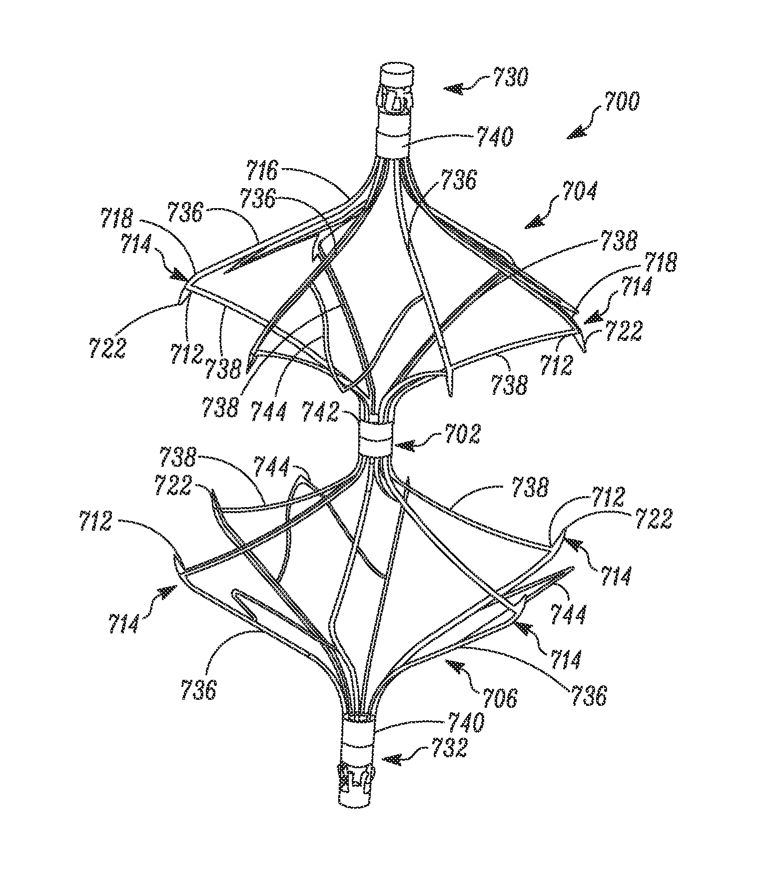
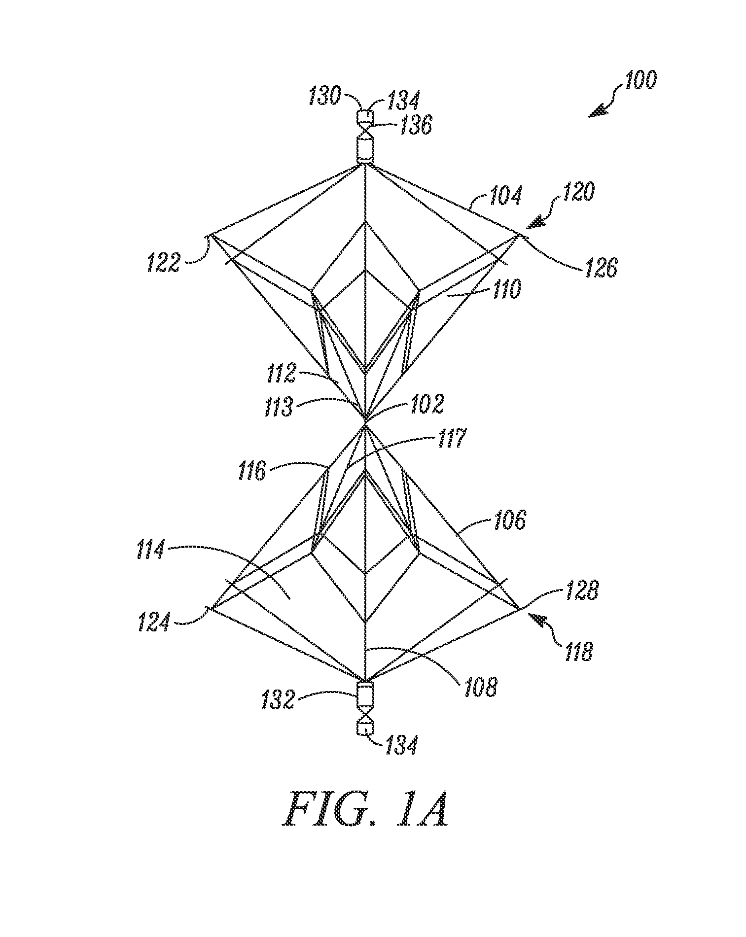
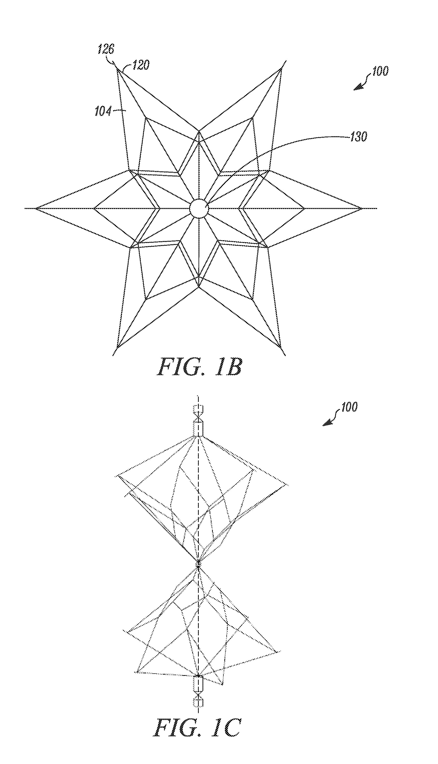
An inferior Vena Cava (“IVC”) filter is formed of two adjacent structures such as polyhedral, each having a number of sides positioned to avoid side-wise contact with the caval wall. The structures form a first filter basket and a second filter basket respectively, with the filter baskets joined by a center structure around a center axis of the IVC filter. In this configuration, the IVC filter advantageously self-aligns within the IVC, while permitting bidirectional or directionally independent deployment, use, and retrieval. While polyhedra may usefully be configured with no sides parallel to the IVC wall to mitigate attachment to the IVC wall, the structures of the filter baskets may also or instead use curved members distal to the center axis that contact the IVC wall only at a single tangent point or area.

Description

CROSS-REFERENCE TO RELATED APPLICATIONS[0001]This application claims the benefit of U.S. Provisional Application No. 61 / 712,562 filed on Oct. 11, 2012, the entire content of which is hereby incorporated by reference.BACKGROUND[0002]1. Field[0003]The invention generally relates to inferior vena cava filters.[0004]2. Description of the Related Art[0005]Inferior Vena Cava (IVC) filters prevent pulmonary embolism by catching blood clots in the vascular system before they reach the lung. IVC filters are used in patients with high risk of pulmonary embolism or when anticoagulation therapy (blood thinner medications) cannot be used. Originally, such filters were placed into human bodies as permanent devices. However, increasing evidence indicated that long term-use leads to complications such as caval occlusion resulting in bilateral severe leg swelling, as well as filter erosion into the caval wall or adjacent organs.[0006]Retrievable IVC filters have been increasingly preferred over perm...

Claims


Application Information

Patent Timeline
Patent Type & Authority Applications(United States)
IPC IPC(8): A61F2/01
CPCA61F2/01A61F2230/005A61F2230/0058A61F2230/0067A61F2230/0086A61F2/0103
Inventor WANG, DANIEL SHENG
Owner WANG DANIEL SHENG
Learn More