
Apparatus and method for driving liquid crystal display device

a liquid crystal display and apparatus technology, applied in static indicating devices, instruments, semiconductor devices, etc., can solve the problems of large size of tfts to meet high-temperature operation characteristics, difficulty in applying the method of varying the level of drive voltage, etc., to achieve enhanced detection temperature application effects, reduce the size of each tft, and enhance the effect of temperature detection

Active Publication Date: 2014-04-24
LG DISPLAY CO LTD
View PDF2 Cites 25 Cited by
  • Summary
  • Abstract
  • Description
  • Claims
  • Application Information

AI Technical Summary

Benefits of technology

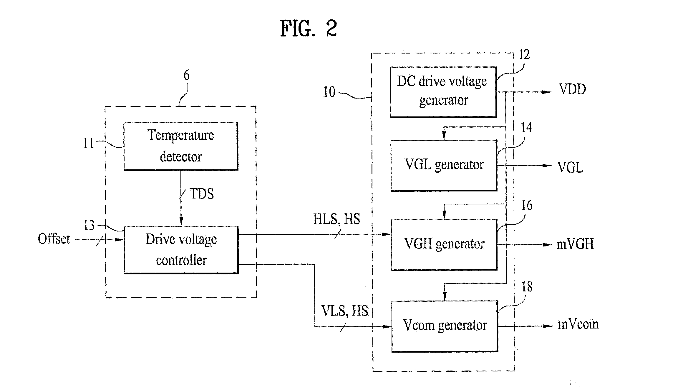
The invention provides an apparatus and method for driving a liquid crystal display device that can stabilize the gate driving circuit by adjusting the levels of the gate driving voltage and common voltage supplied to the panel in response to ambient temperature variations. This helps to prevent degraded picture quality caused by variations in the image display voltage. The apparatus can detect and measure temperatures at different times, allowing for accurate temperature detection and control. The level of common voltage supplied to the panel is also adjusted based on the detected temperatures to reduce level variation of the image display voltage caused by the kick-back voltage. This results in a more stable and high-quality display.

Problems solved by technology

However, in a structure in which the gate drive circuit is formed at the liquid crystal panel, there is a difficulty in applying the method of varying the level of the drive voltage because thin film transistors (TFTs) of the gate drive circuit are made of amorphous silicon (a-Si).
In other words, the liquid crystal panel which is of an active matrix type may have a difficulty in application thereof because the range of the voltage to operate liquid crystals is wide.
Furthermore, TFTs have a large size to meet high-temperature operation characteristics thereof.
As a result, the gate drive circuit becomes unstable.
For this reason, degradation of picture quality caused by flicker or the like may occur.

Method used


Image

  • Apparatus and method for driving liquid crystal display device
  • Apparatus and method for driving liquid crystal display device
  • Apparatus and method for driving liquid crystal display device

Examples


Embodiment Construction

[0031]Reference will now be made in detail to the preferred embodiments of the invention, examples of which are illustrated in the accompanying drawings.

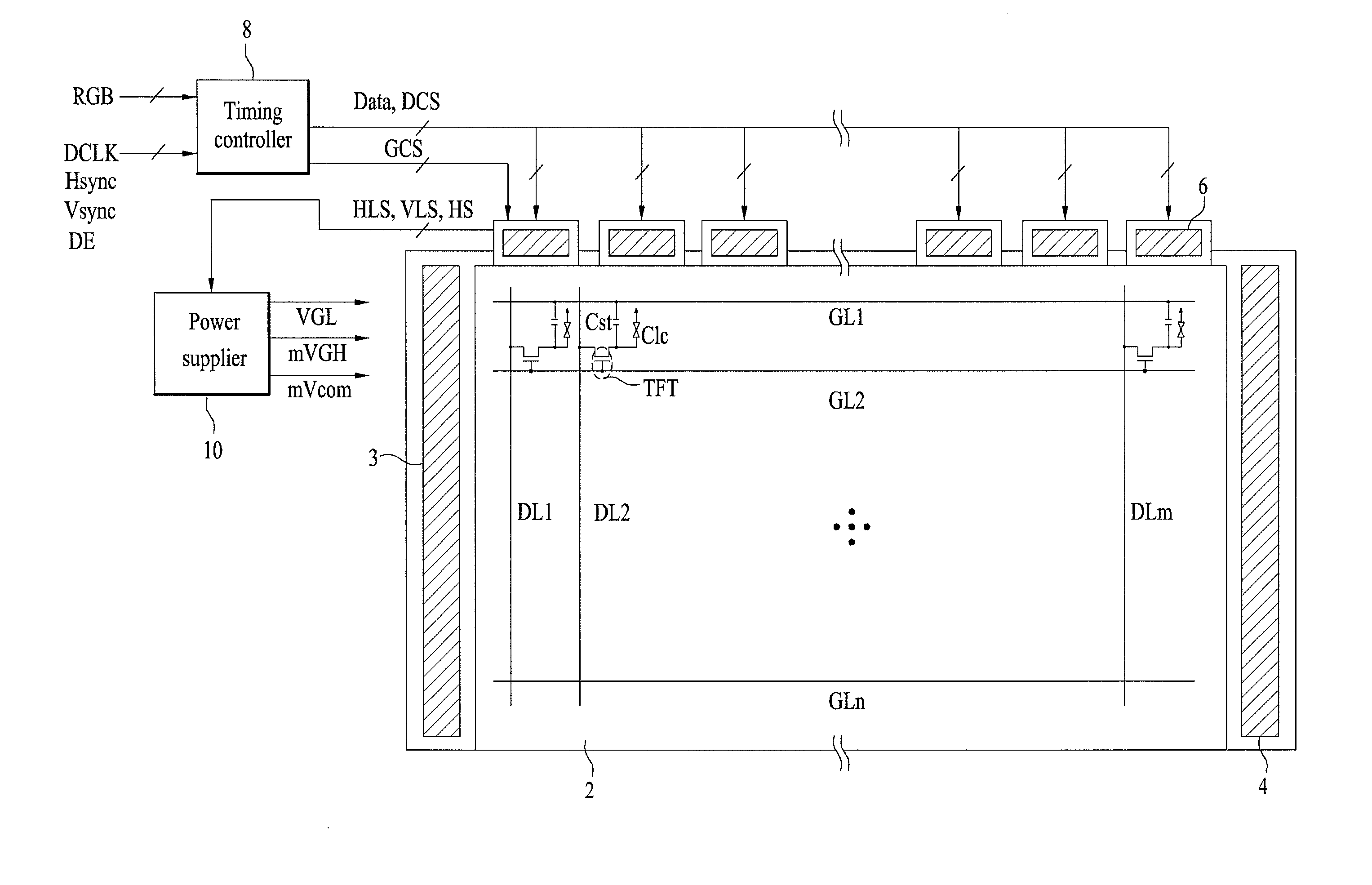
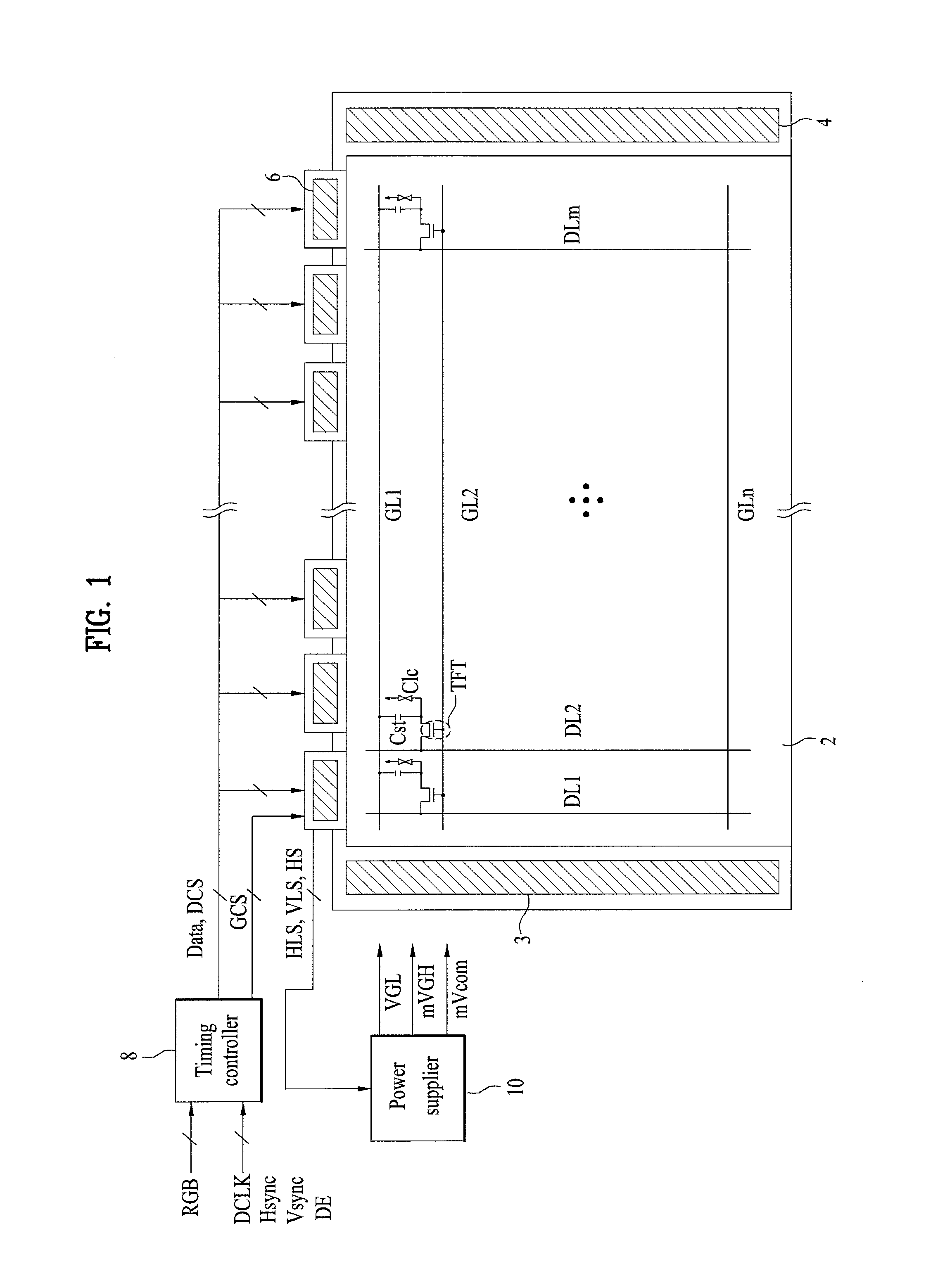
[0032]FIG. 1 is a configuration diagram illustrating an apparatus for driving a liquid crystal display (LCD) device in accordance with an example embodiment of the invention.

[0033]The LCD device driving apparatus illustrated in FIG. 1 includes a liquid crystal panel 2 including a plurality of pixel regions to display an image, at least one gate driver (in this example, two gate drivers 3 and 4 in the illustrated instance) formed in a non-display area of the liquid crystal panel 2, to drive a plurality of gate lines GL1 to GLn of the liquid crystal panel 2, and a data driver 6 for not only driving a plurality of data lines DL1 to DLm of the liquid crystal panel 2, but also setting detectable temperatures for different temperature detection time points, detecting ambient temperature at each of the temperature detection time points, an...


PUM


Abstract

Discussed are an apparatus and method for driving a liquid crystal display device, whereby the apparatus includes a data driver for driving data lines of a liquid crystal panel, setting detectable temperatures for different temperature detection time points, detecting an ambient temperature at each temperature detection time point, and outputting a gate drive voltage variation signal and a common voltage variation signal in accordance with the set and detected temperatures at each temperature detection time point, and a power supplier for varying levels of a gate drive voltage and a common voltage in accordance with the gate drive voltage variation signal and the common voltage variation signal, and supplying the gate drive voltage and common voltage to a gate driver and the liquid crystal panel, respectively.

Description

[0001]This application claims the priority benefit of Korean Patent Application No. 10-2012-0122532, filed on Oct. 31, 2012 which is hereby incorporated by reference as if fully set forth herein.BACKGROUND OF THE INVENTION[0002]1. Field of the Invention[0003]Embodiments of the invention relate to an apparatus and method for driving a liquid crystal display device, which are capable of stabilizing a gate driving circuit through variation of levels of a gate driving voltage and a common voltage supplied to a liquid crystal panel in accordance with an ambient temperature, and preventing degradation of a picture quality through reduction of a level variation of an image display voltage depending on a kick-back voltage (ΔVp).[0004]2. Discussion of the Related Art[0005]Liquid crystal display (LCD) devices display an image using electrical and optical properties of liquid crystals. Liquid crystals exhibit different anisotropic properties in longer and shorter-axis directions of liquid crys...

Claims


Application Information

Patent Timeline
Patent Type & Authority Applications(United States)
IPC IPC(8): G09G3/36
CPCG09G3/3696G09G3/3655G09G3/3677G09G2320/0219G09G2320/041Y02E10/52Y02E10/547G09G3/36H01L31/02366H01L31/048H01L31/068H01L31/0543
Inventor JANG, DAHEEKIM, MINPYOKIM, BOJOONGHONG, SEEUNKIM, TAEYOONKIM, HWANYEONHONG, JONGKYOUNG
Owner LG DISPLAY CO LTD
Learn More