
Blind spot monitor assembly

a monitor and blind spot technology, applied in the direction of manufacturing tools, using reradiation, instruments, etc., can solve the problems of damage to the outer face of the electromagnetic radiation,

Active Publication Date: 2014-04-24
TOYOTA JIDOSHA KK
View PDF5 Cites 40 Cited by
  • Summary
  • Abstract
  • Description
  • Claims
  • Application Information

AI Technical Summary

Benefits of technology

The patent text describes a bracket that is used to attach a blind spot monitor to a vehicle panel. The bracket has multiple apertures for fasteners that are positioned so that they align with corresponding apertures in the blind spot monitor. The bracket also has strengthening ribs that increase its durability and resilience. The bracket can be first fixed to the blind spot monitor and then fixed to the vehicle panel or permanently welded. The bracket also has rounded protrusions that help guide the blind spot monitor into the bracket and ensure proper alignment with the mounting posts of the vehicle. The technical effects of this design include secure attachment of the blind spot monitor to the vehicle panel and proper alignment during installation.

Problems solved by technology

However, blind spot monitors have a sensitive, electromagnetic radiation emitting outer face which can be damaged with impact by debris.

Method used


Image

  • Blind spot monitor assembly
  • Blind spot monitor assembly
  • Blind spot monitor assembly

Examples


Embodiment Construction

[0018]A bracket for protecting a blind spot monitor mounted behind a rear tire in a vehicle is provided. The bracket can shield an outer face of the blind spot monitor from debris thrown up by the rear tire. The bracket can additionally affix to the blind spot monitor prior to the assembly being mounted on the vehicle to reduce the installation burden and make the assembly easier to install. As such, the bracket has use as a component for the motor vehicle.

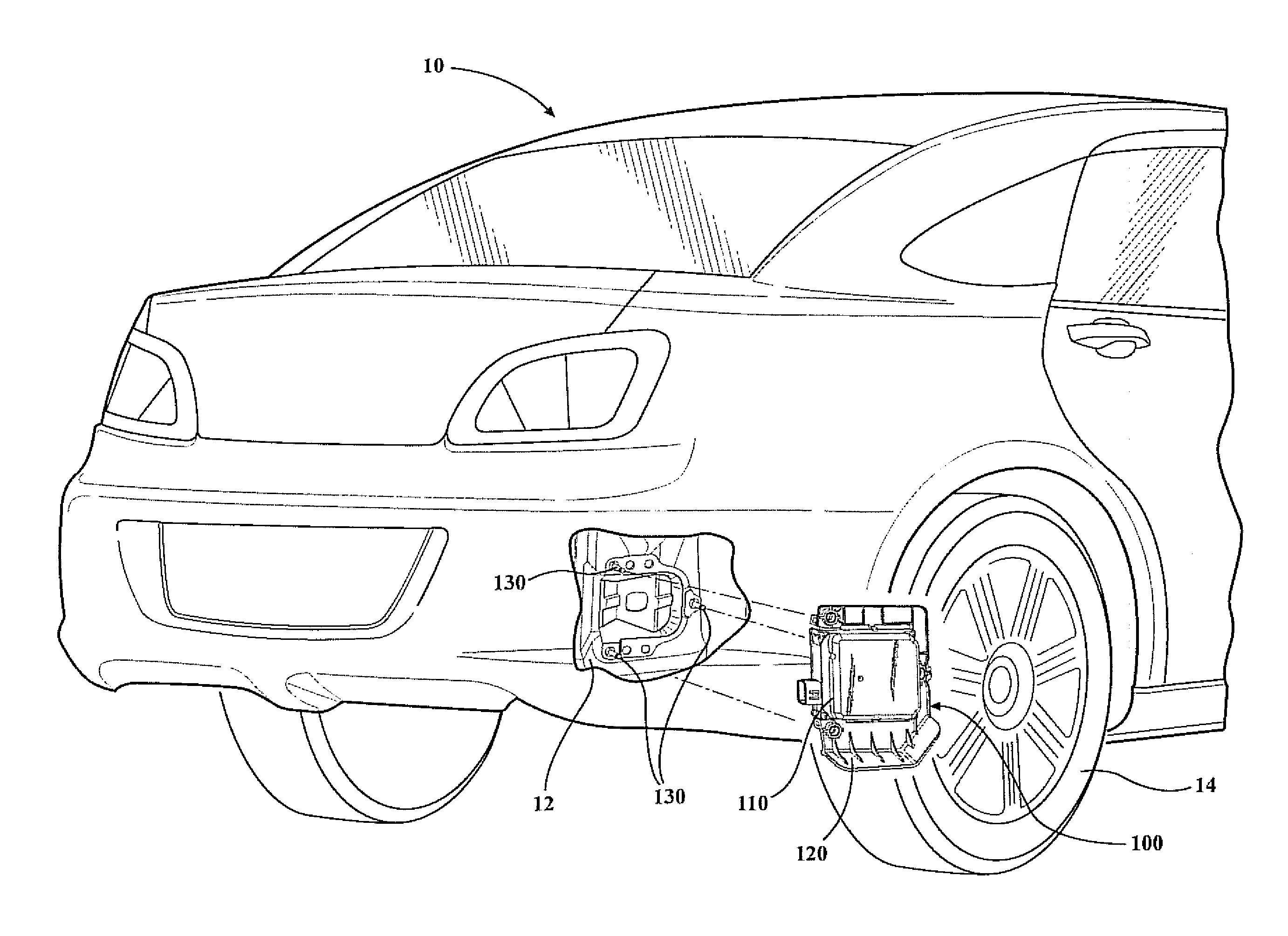
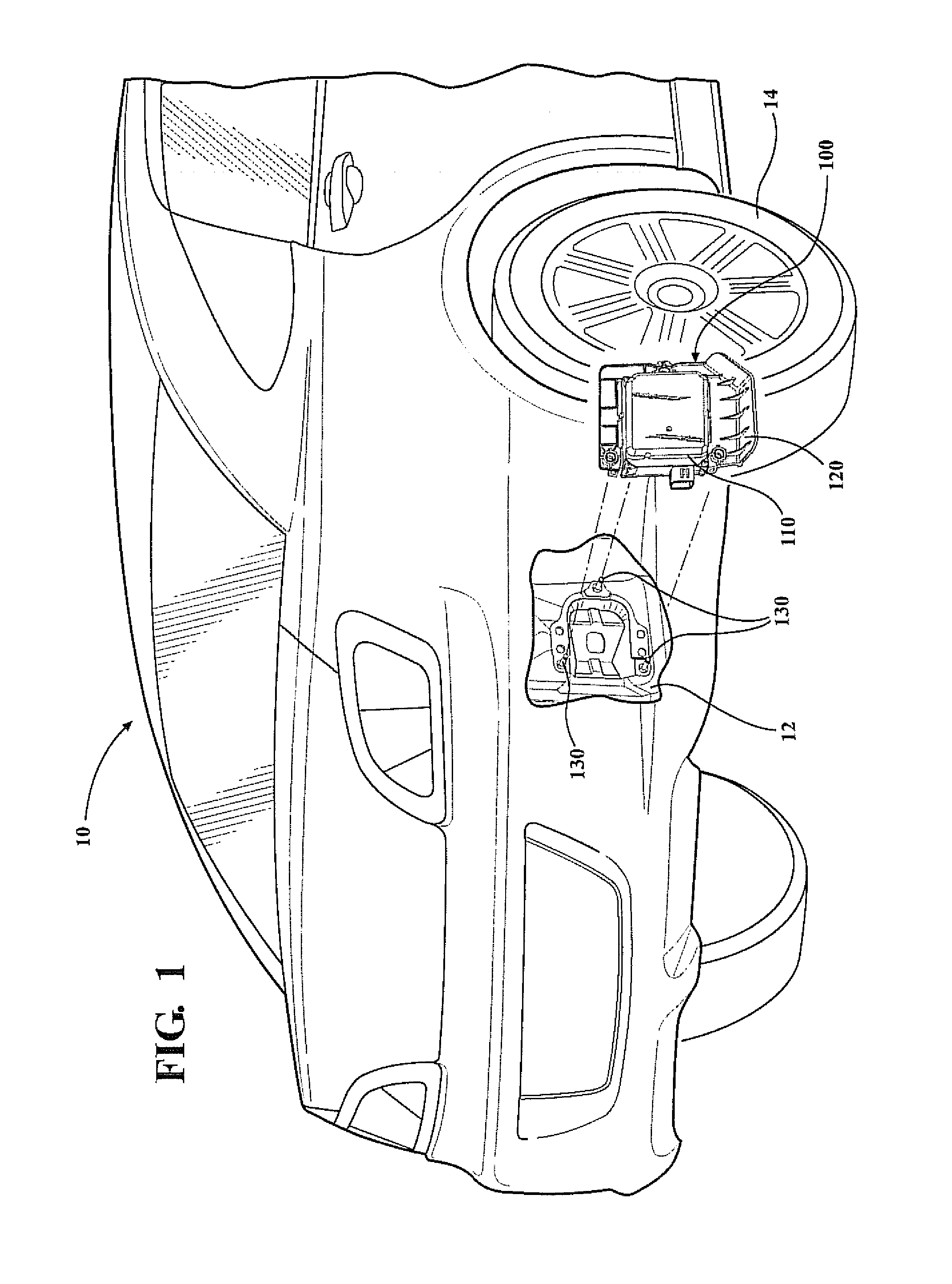
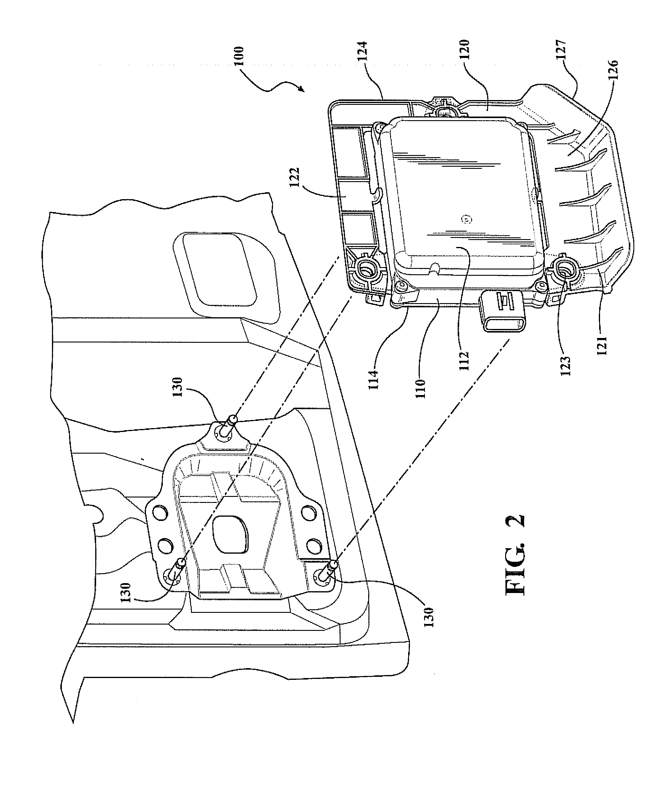
[0019]Referring now to FIG. 1, a motor vehicle 10 with a rear panel 12 and mounting posts 130 is generally shown along with a blind spot monitor assembly 100 comprising a blind spot monitor 110 and a bracket 120. The blind spot monitor assembly 100 is installed on the rear panel 12 of the motor vehicle 10 using a plurality of mounting posts 130. In the present embodiment, the blind spot monitor assembly 100 can be secured to the mounting posts 130 using fasteners or through welding, although other methods will be readily apparent ...


PUM

PropertyMeasurementUnit
volumeaaaaaaaaaa
perimeteraaaaaaaaaa
resilientaaaaaaaaaa

Abstract

A bracket for a vehicle blind spot monitor. The bracket can have upper and bottom members that are spaced apart from each other and connected by a side member. The upper, bottom and side members of the bracket can also form an opening where a blind spot monitor can be located. The bottom member can have a debris-blocking flange that protects or shields the outer radar surface from debris such as rocks, sand, etc., that are thrown up from a road surface towards the blind spot monitor. The bracket can have a plurality of protrusions to guide the blind spot monitor into the bracket opening. The bracket additionally features clips that affix the blind spot monitor to the bracket prior to installation on the vehicle.

Description

FIELD OF THE INVENTION[0001]The present invention relates to a blind spot monitor assembly for a motor vehicle, and in particular to a bracket that affixes to a blind spot monitor module prior to mounting the blind spot monitor assembly on a motor vehicle.BACKGROUND OF THE INVENTION[0002]Blind spot monitors have been provided on vehicles to alert a driver when an object or vehicle is in a spot that the driver cannot readily see. Blind spot monitors have been placed behind a rear wheel of the vehicle and fixed to the rear panel, with this location allowing the monitor to detect objects that are present in a location not able to be viewed by the driver via side mirrors and / or a rear view mirror. However, blind spot monitors have a sensitive, electromagnetic radiation emitting outer face which can be damaged with impact by debris. Accordingly, there exists a need in the art to provide a structure that will protect the blind spot monitor from debris from the road surface.[0003]Furthermo...

Claims


Application Information

Patent Timeline
Patent Type & Authority Applications(United States)
IPC IPC(8): H05K7/00B23P11/00
CPCB60R16/0239G01S2013/93275G01S7/027Y10T29/49947
Inventor YAMASAKI, BRYAN ELSELOTA, CHARAN SINGH
Owner TOYOTA JIDOSHA KK
Learn More