
Connector Block with Spring-Loaded Electrical Terminal Assemblies

Inactive Publication Date: 2014-04-24
PHOENIX CONTACT DEVMENT & MFG
View PDF0 Cites 16 Cited by
  • Summary
  • Abstract
  • Description
  • Claims
  • Application Information

AI Technical Summary

Benefits of technology

The invention is a connector block with improved spring terminals that includes a spring retainer that is not formed as part of the current bar, which is a relatively low cost member. This allows the spring terminal to be installed in the connector block at low cost. The spring retainer is preferably formed as a stamped member from metal plate. The spring terminal has the advantage of being a low-cost component with reduced manufacturing cost. Identical spring retainers can be used with connector blocks having multiple current bars with different bar geometries, simplifying and reducing inventory costs. The spring terminal is easy to assemble.

Problems solved by technology

The current bar is made of expensive electrically conductive material (typically a copper alloy).
Forming the spring retainer in the current bar is expensive both in material cost and manufacturing cost.
Manufacture and assembly of the spring with the current bar is relatively expensive.
The U-shaped member is a relatively large component and so material cost is high.

Method used


Image

  • Connector Block with Spring-Loaded Electrical Terminal Assemblies
  • Connector Block with Spring-Loaded Electrical Terminal Assemblies
  • Connector Block with Spring-Loaded Electrical Terminal Assemblies

Examples


Embodiment Construction

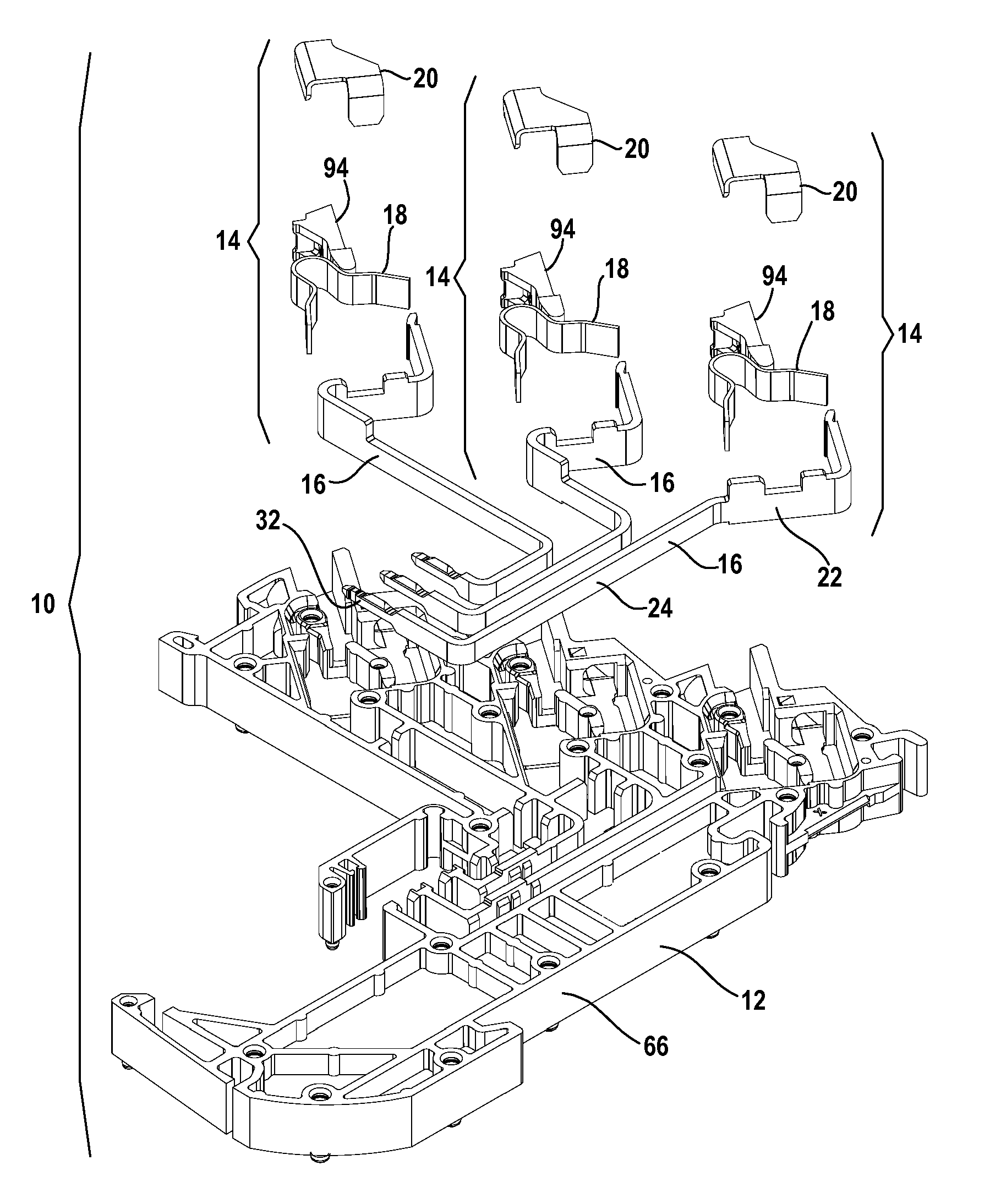
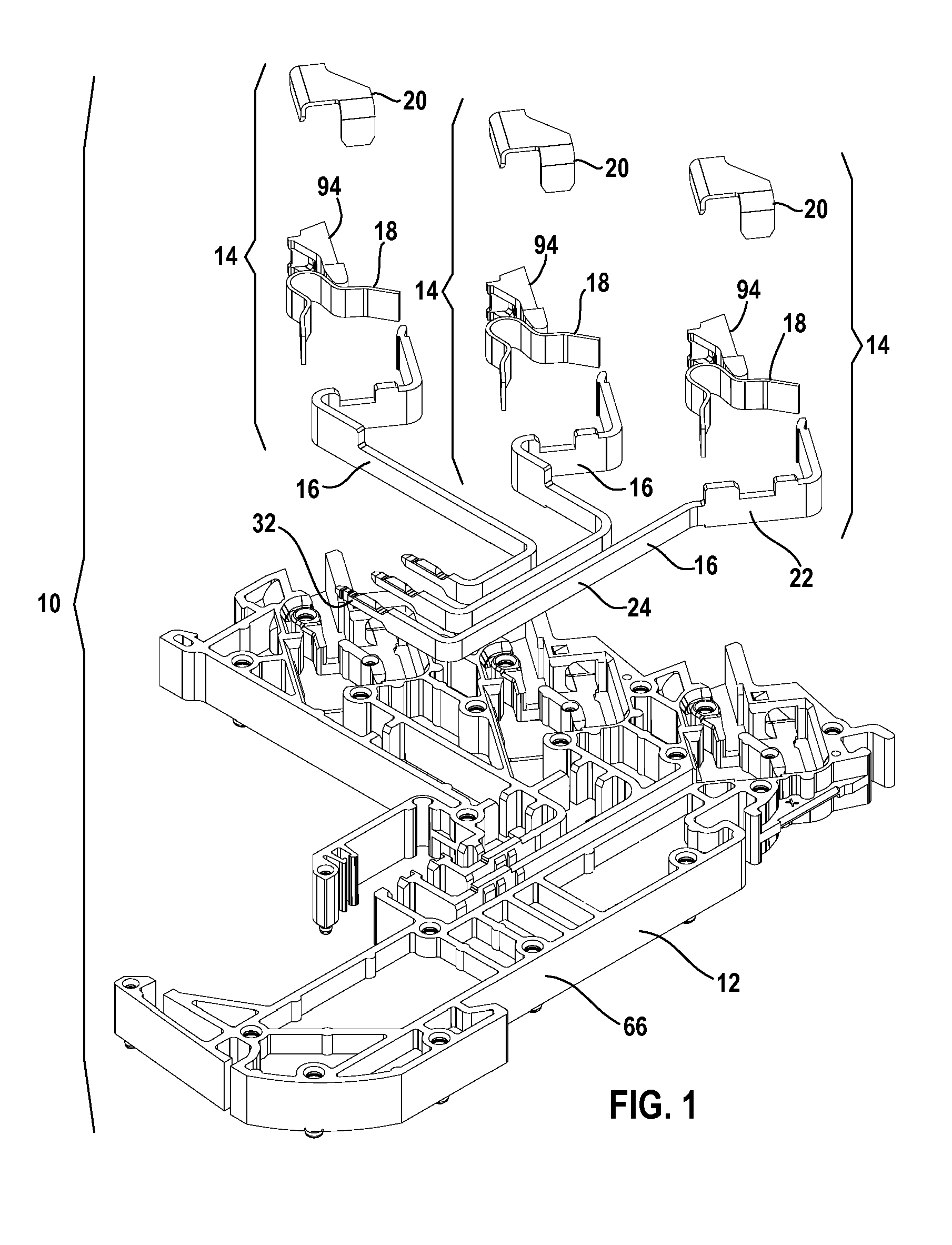
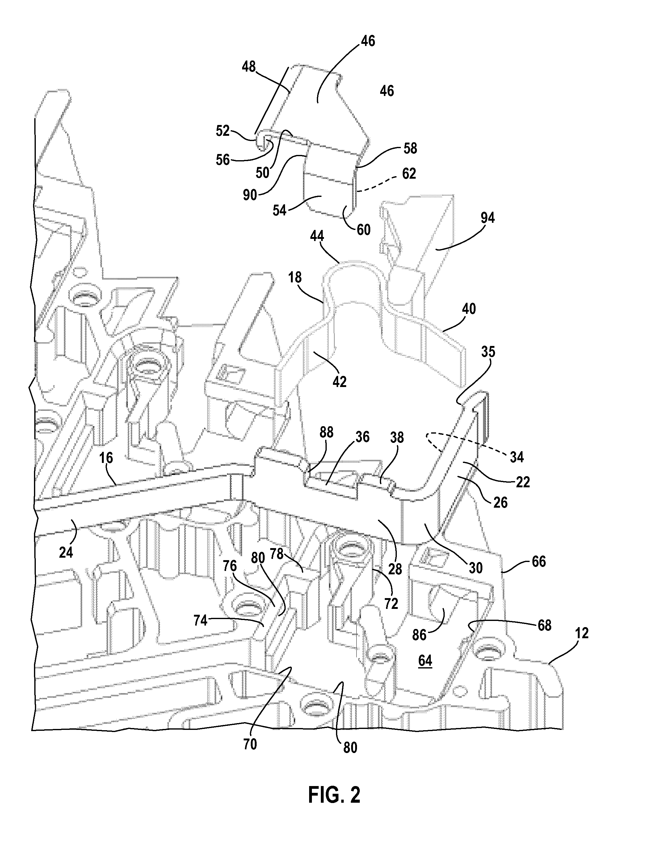
[0018]The figures illustrate a connector block 10 for forming electrical connections between wire conductors and current bars 16 carried by the connector block 10. The connector block 10 includes a housing 12 and a number of like electrical terminal or spring terminal assemblies 14 in the housing 12, each terminal assembly 14 configured to form an electrical connection between a wire conductor and a respective current bar 16. Because in the illustrated embodiment the terminal assemblies 14 are identical assemblies (although each of the current bars have different geometries), only a single terminal assembly will be described in detail.

[0019]The terminal assembly 14 includes an end portion of a conductor bar or current bar 16, a spring 18, and a support plate or spring retainer 20, the spring retainer 20 a body separate from and not integral with the current bar 16 or the spring 18. A respective pusher tool or actuator tool 94 is associated with each terminal assembly 14 and is used ...


PUM


Abstract

An electrical terminal or spring terminal for forming an electrical connection between a wire conductor and a current bar includes a spring and a spring retainer, the spring retainer not integral with the spring and not integral with the current bar. Engageable abutment surfaces on the spring retainer and the current bar cooperate to transfer spring force to the current bar.

Description

FIELD OF THE INVENTION [0001]The invention relates to electrical terminal assemblies for forming electrical connections between wire conductors and rigid conductors, and in particular screwless electrical terminal assemblies in which a spring presses the wire conductor against the rigid conductor.BACKGROUND OF THE INVENTION[0002]Connector blocks that include “screwless” electrical terminals or spring terminals for forming electrical connections between rigid conductors or current bars in the connector block and wire conductors are known. The spring terminal utilizes a compressed spring that generates a spring force pressing the wire conductor against the current bar to form the electrical connection therebetween.[0003]A known type of spring terminal utilizes the current bar as a spring retainer. A portion of the current bar is formed as a spring retainer that retains both ends of the compressed spring. The current bar is made of expensive electrically conductive material (typically ...

Claims


Application Information

Patent Timeline
IPC IPC(8): H01R4/48H01R9/24H01R13/514
CPCH01R9/2616H01R4/48185H01R9/26H01R4/48365H01R4/48H01R9/24H01R13/514
Inventor BARBER, TERRY LEECORRELL, MICHAEL ANTHONYSOMMER, MELISSA ANN
Owner PHOENIX CONTACT DEVMENT & MFG
Learn More