Submarine

a technology for submersibles and icebreakers, applied in underwater equipment, waterborne vessels, water cleaning, etc., can solve the problems of not being able to apply icebreakers in ice layers of a greater thickness, particularly in the direction of oil spills,

Active Publication Date: 2014-05-01
THYSSENKRUPP MARINE SYST GMBH
View PDF6 Cites 6 Cited by
  • Summary
  • Abstract
  • Description
  • Claims
  • Application Information

AI Technical Summary

Benefits of technology

[0006]The basic idea of the invention is to combat oil which with oil production in the Arctic collects in an oil bubble below a sheet of ice after spills, from below the sheet of ice by way of submarine submerged to the oil bubble. I.e. according to the invention, a submarine is provided, which is designed for combating oil at submerged travel or whilst submerged. Accordingly, it is no longer necessary to break open the ice sheet located over the oil, in order to have access to the oil, before combating the oil.
[0010]In an advantageous, alternative design, the snout can be designed in a flexible manner, wherein the snout is fastened in a section adjacent to its free end, on an ROV (remotely operated vehicle), i.e. onto a remotely controlled, in particular cable-led underwater vehicle. Accordingly, the snout can be a hose which is to say a flexible tube, which for sucking oil is wound off from a motorically actuated hose drum which is arranged in the intermediate space between the pressure hull of the submarine and the upper deck, wherein the free hose end with the suction nozzle or suction cup fastened thereto, is moved to the oil bubble in a remote-controlled manner by the ROV, on which the hose is fastened. The use of a flexible snout has the advantage that no rigid connection exists between the suction head and the submarine. Contacts of the suction head or of the snout with the lower side of the ice do not endanger the submarine or the snout. Moreover, movements of the submarine no longer have an effect on the positioning of the suction head, since the positioning of the snout and thus of the suction head is assumed by the ROV. A particularly efficient sucking-away of oil is possible by way of this.

Problems solved by technology

If however oil spills occur during the production, combating the oil spillage has been found to be particularly problematic if the oil collects below the surface of the ice and is thus not directly accessible.
The application of ice breakers however is no longer possible with ice layers of a greater thickness.

Method used


Image

  • Submarine
  • Submarine
  • Submarine

Examples


Embodiment Construction

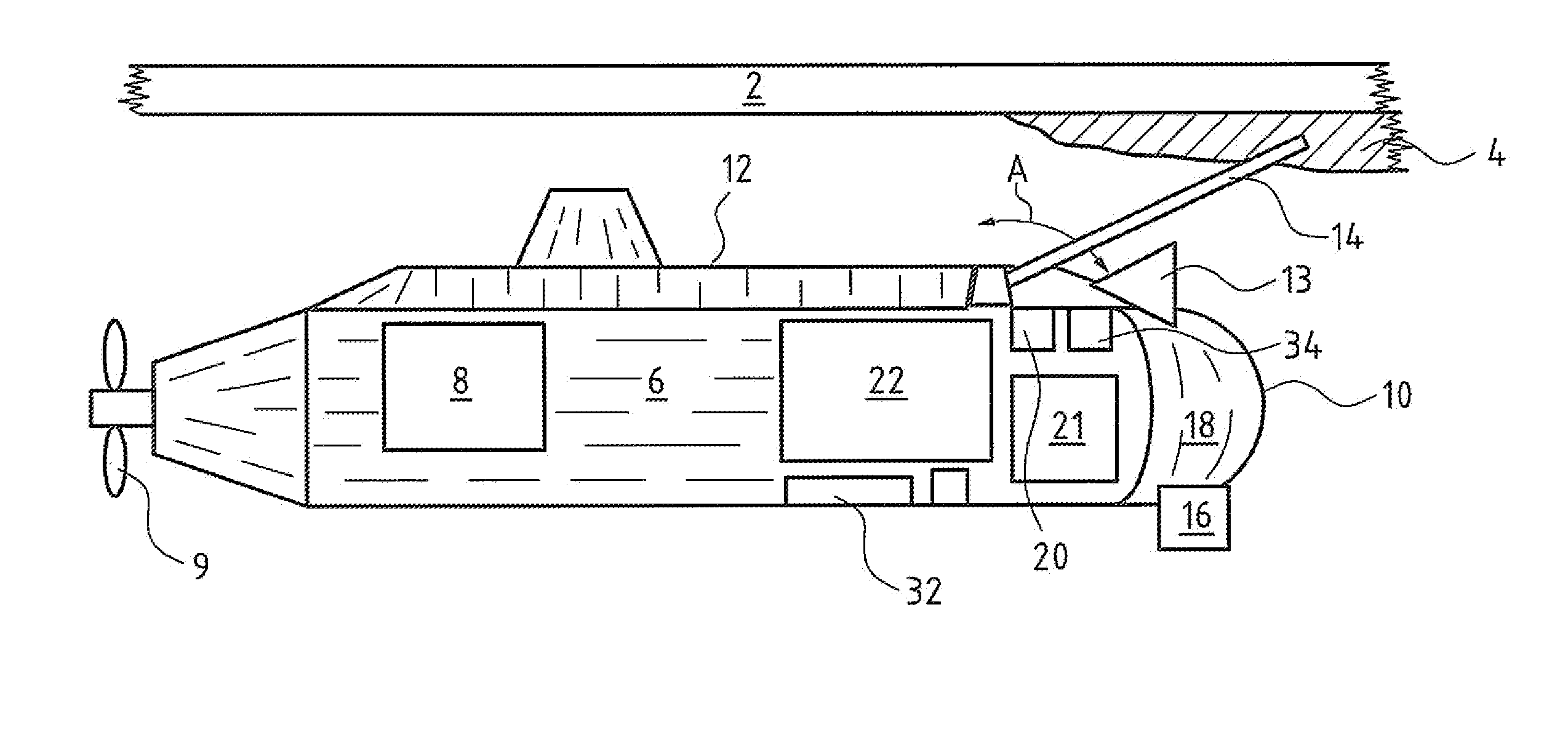
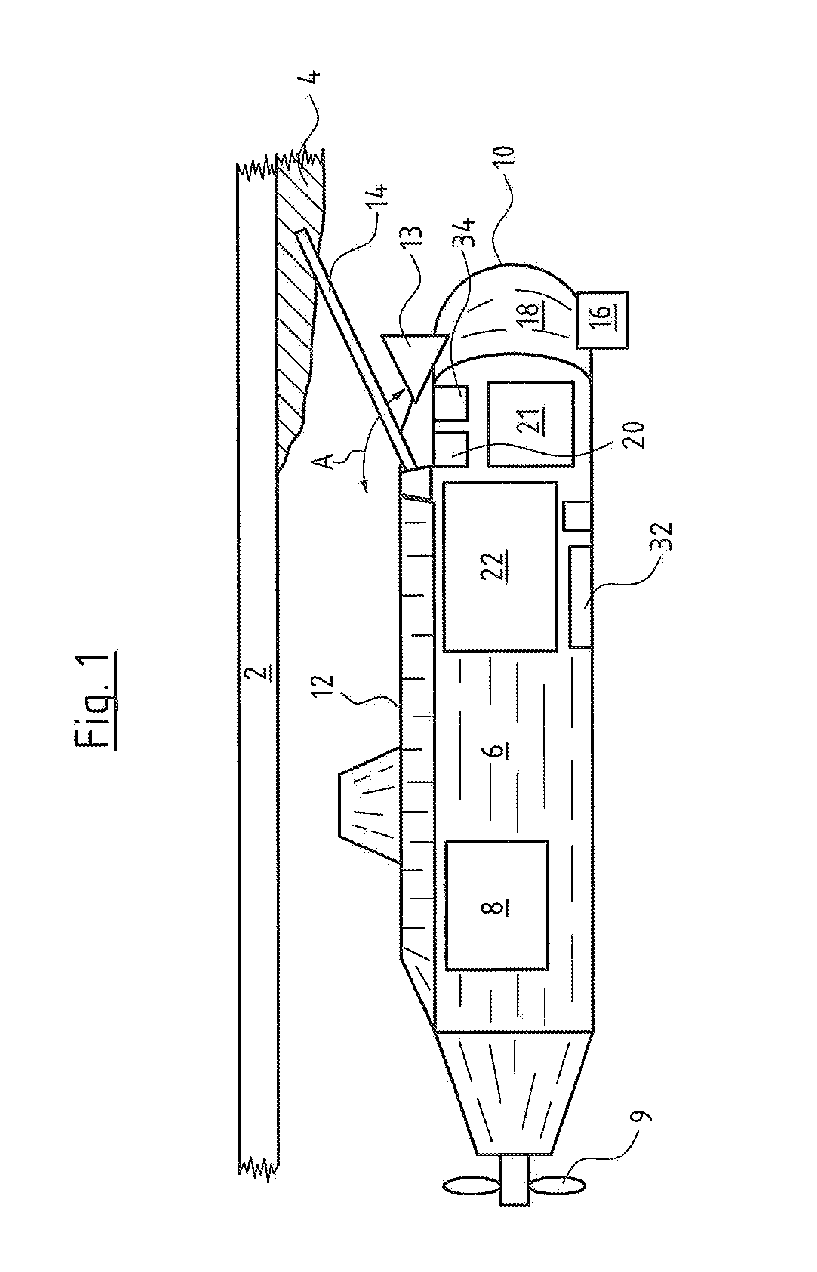
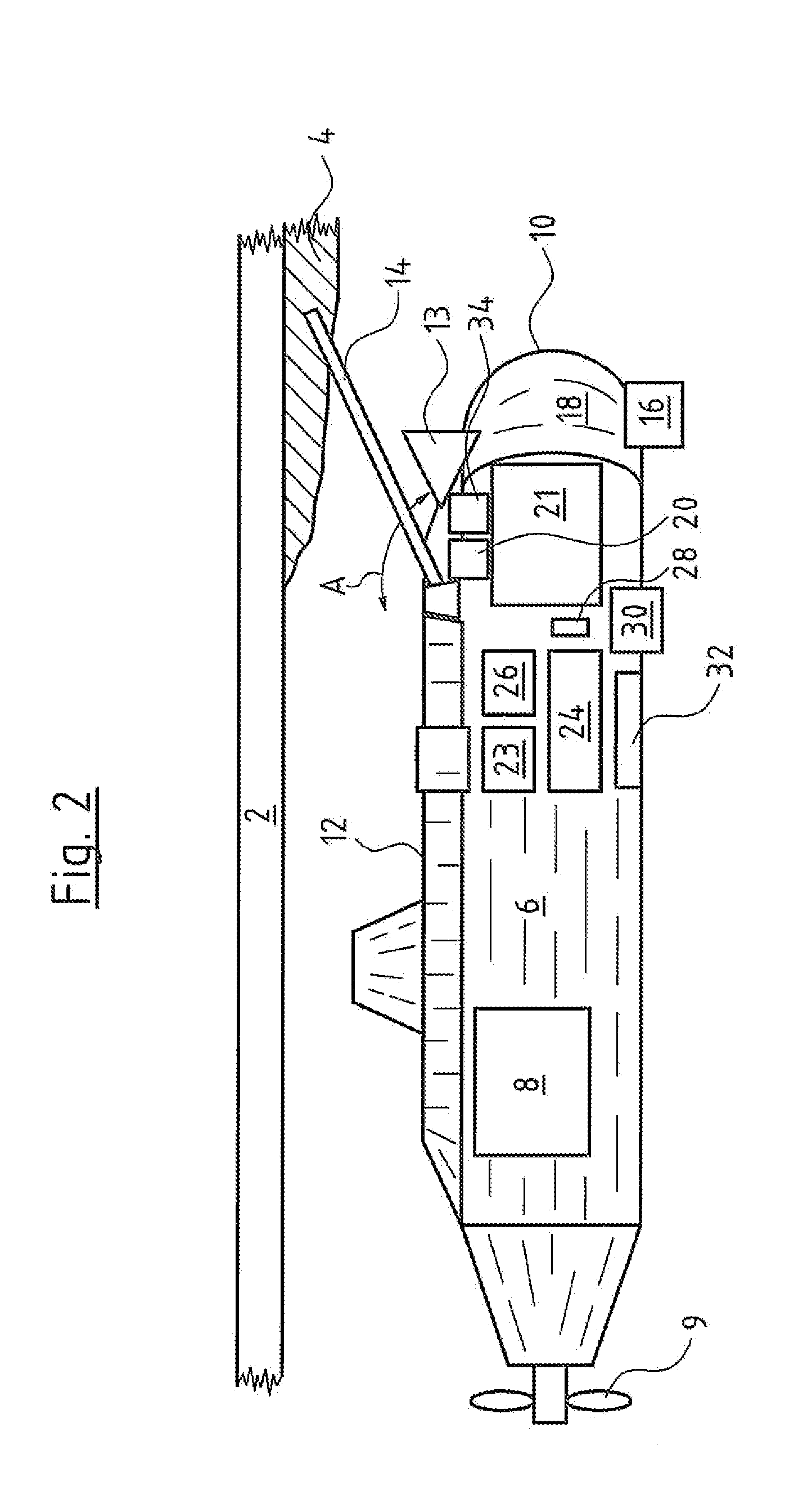
[0026]Referring to the drawings in particular, FIGS. 1 to 3 in each case represent a submarine submerged below an ice sheet 2. Oil which has spilled during oil production has collected into an oil bubble 4 directly below the lower side of the ice sheet 2.

[0027]The submarines according to FIGS. 1 to 3 in each case comprise a pressure hull 6. These submarines in each case are driven by an electric drive 8 which is independent of external air, is arranged in the pressure hull 6 and drives a propeller 9. The pressure hulls 6 of the shown submarines are surrounded by an outer hull 10 on the bow side and on the upper side. A section of the outer hull 10 which is arranged on the upper side of the pressure hull 6 in a manner distanced to the pressure hull 6 forms an upper deck 12 of the submarines. Moreover, the three represented submarines in each case comprise an oil suction device. The submarines are moreover each equipped with an oil locating device 13 which is formed by a sonar device ...


PUM


Abstract

A submarine is designed for combating oil when submerged. The submarine includes a snout (14, 36) which is conduit-connected to a conduit leading into the submarine. The snout (14, 36) is part of an oil suction device and / or part of a device for bringing out an oil decomposition substance. The snout (14) may be designed in a rigid manner and be pivotable from a position between a pressure hull (6) of the submarine and an outer hull (10) forming an upper deck (12) of the submarine, into a position outside the outer hull (10). The snout (36) may also be designed in a flexible manner, wherein the snout (36) is fastened in a section adjacent to a free end, on an ROV (40).

Description

CROSS REFERENCE TO RELATED APPLICATIONS[0001]This application is a United States National Phase Application of International Application PCT / EP2012 / 060761 filed Jun. 6, 2012 and claims the benefit of priority under 35 U.S.C. §119 of German Patent Application DE 10 2011 104 122.6 filed Jun. 7, 2011, the entire contents of which are incorporated herein by reference.FIELD OF THE INVENTION[0002]The invention relates to a submarine.BACKGROUND OF THE INVENTION[0003]Offshore oil production in the Arctic has become economical due to the increased oil demand and the reduction of other reserves. If however oil spills occur during the production, combating the oil spillage has been found to be particularly problematic if the oil collects below the surface of the ice and is thus not directly accessible. Ice layers up to a certain thickness can be broken with ice breakers and the oil located therebelow can be combated by way of scooping up, flaring off or by way of the addition of oil decomposit...

Claims


Application Information

Patent Timeline
Patent Type & Authority Applications(United States)
IPC IPC(8): B63G8/00
CPCB63G8/001B63B35/32E02B15/046Y02A20/204
Inventor BRANDT, HENDRIKFISCHER, JENS
Owner THYSSENKRUPP MARINE SYST GMBH
Why Eureka
Try Eureka