Fluid control system

a control system and flow rate technology, applied in the direction of valve operating means/releasing devices, process and machine control, instruments, etc., can solve the problems of control becoming unstable, waste of time for the first several control loops until the flow rate adjusting valve actually begins moving,

Active Publication Date: 2014-05-01
HORIBA STEC CO LTD
View PDF23 Cites 51 Cited by
  • Summary
  • Abstract
  • Description
  • Claims
  • Application Information

AI Technical Summary

Benefits of technology

[0012]In accordance with this arrangement, even though the dead zone in the flow rate adjusting valve fluctuates due to the type, pressure, and temperature of the fluid, since the initial value of the driving signal, namely a first value of the driving signal to be given to the flow rate adjusting valve from the fully closed state, changes in accordance with the type, pressure, and temperature of the fluid, at a time when control of the flow rate adjusting valve is initiated from the fully closed state in order to make the measured flow rate equal to the target flow rate, it is possible to make the flow rate reach the target flow rate quickly and to control the flow rate stably irrespective of the ambient situation.
[0013]The optimum initial value of the driving signal determined by the use of the type, pressure, or temperature of the fluid as the parameter has an instrumental error and changes in accordance with change over time of properties of the flow rate adjusting valve or its peripheral devices.
[0014]In order to cope with this, it is preferable to provide a learning function.
[0015]As a concrete embodiment of this, it is preferable that the control circuit comprises a memory part that memorizes in pairs a starting up driving signal value, being the driving signal value at a time when the flow rate adjusting valve begins moving from a fully closed state, and at least one of the type, pre...

Problems solved by technology

Then, if the feedback control for calculating the driving signal value (the applied voltage) of the flow rate adjusting valve, in accordance with the deviation between the target flow rate and the measured flow rate, is performed from the target flow rate, the applied voltage calculated in the first several control loops does not exceed the threshold so that the time for the first several control...

Method used


Image

  • Fluid control system
  • Fluid control system
  • Fluid control system

Examples


Embodiment Construction

[0025]An embodiment of this invention will be explained with reference to drawings.

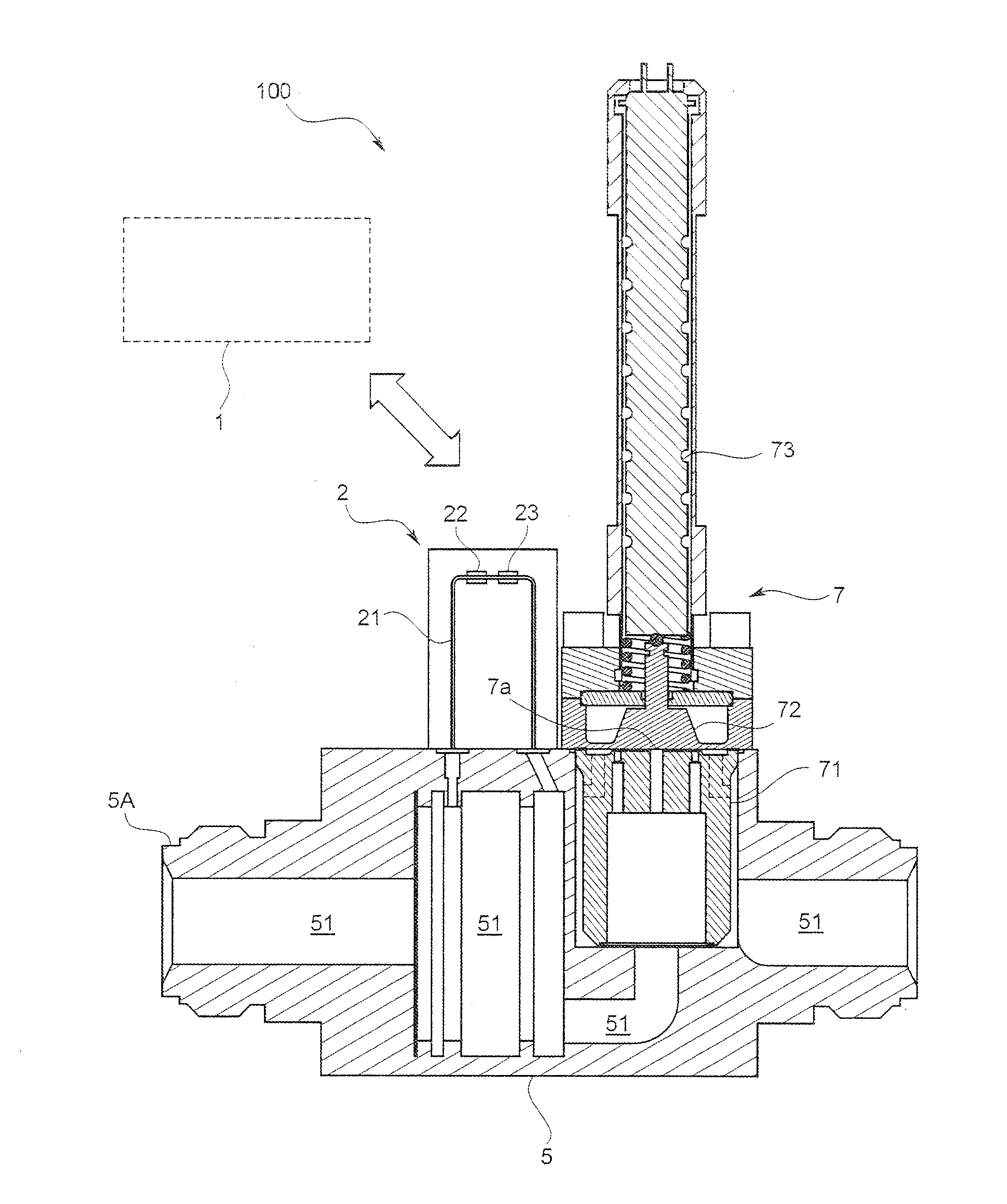
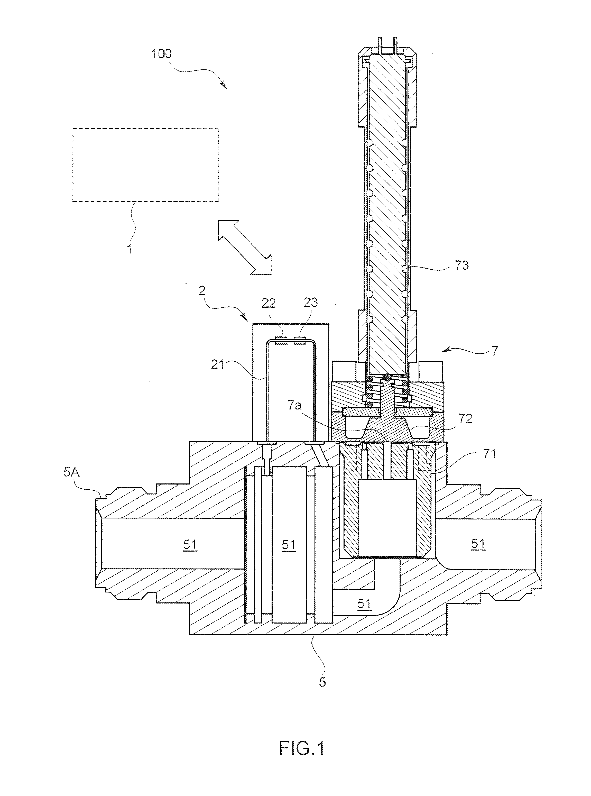
[0026]This embodiment of a fluid control system is, as shown in FIG. 1, to control the flow rate of a fluid such as a material gas used for manufacturing a semiconductor, and comprises a body 5 into which a flow channel 51 where the fluid flow penetrates, a flow rate adjusting valve 7 arranged on the flow channel 51, a flow rate measuring device 2 that is arranged in the upstream side of the flow rate adjusting valve 7 and that measures the flow rate of the fluid flowing in the flow channel 51 and a control circuit 1 that controls the open degree of the flow rate adjusting valve 7 so as to make the measured flow rate measured by the flow rate measuring device 2 equal to a previously determined target flow rate.

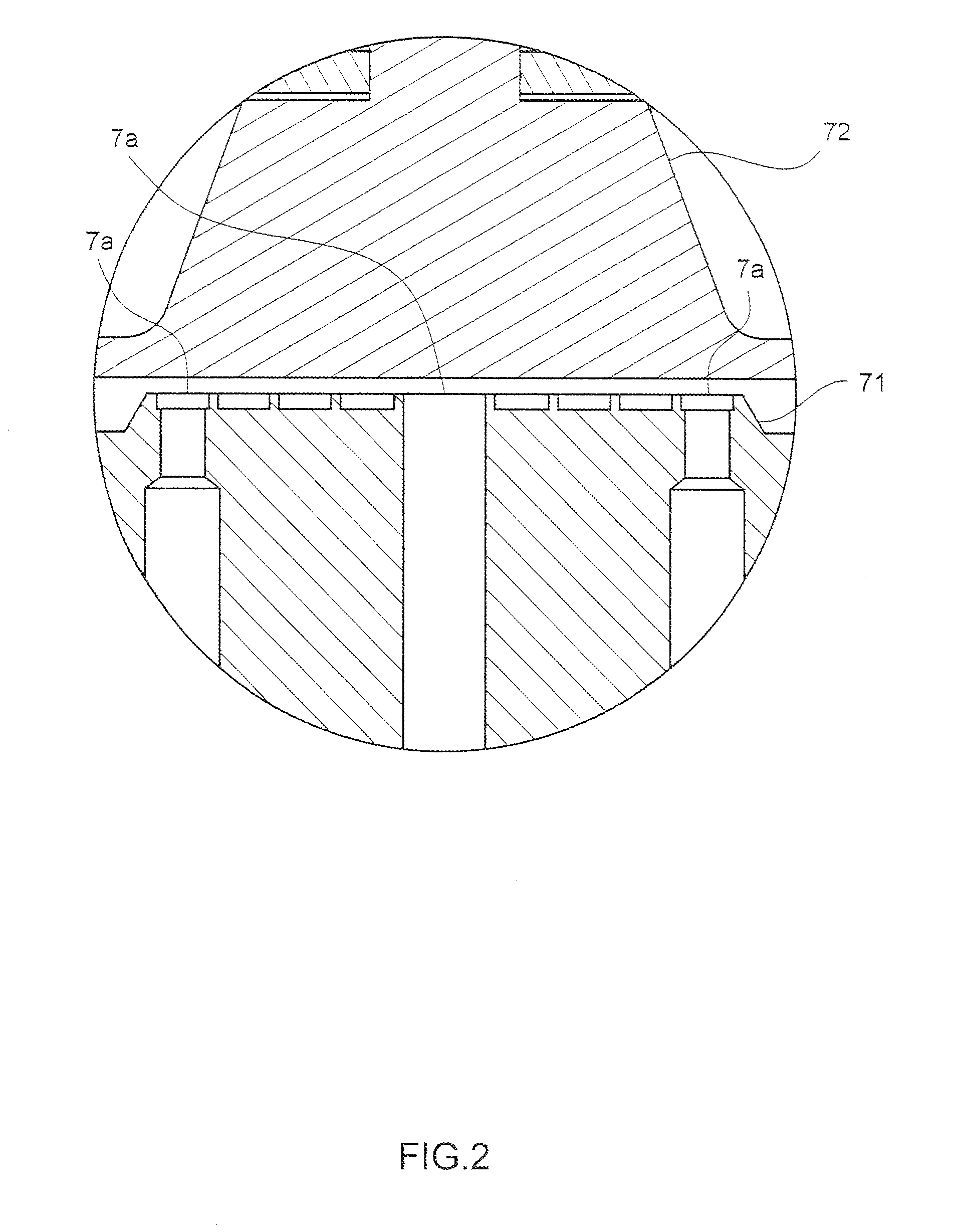
[0027]The flow rate adjusting valve 7 comprises, as shown in FIG. 1 and FIG. 2, a valve seat 71 where an opening 7a from which the fluid flowing through the flow channel 51 flows out is formed, ...


PUM


Abstract

At a time when control of a flow rate adjusting valve is initiated from a fully closed state in order to make a measured flow rate equal to a target flow rate, an initial value of a driving signal is set as a parameter by making use of at least one of the type, pressure, and temperature of a fluid.

Description

FIELD OF THE ART[0001]This invention relates to a fluid control system that controls a flow rate of a material gas used in, for example, a semiconductor manufacturing process.BACKGROUND ART[0002]This type of fluid control system has a flow rate sensor and a flow rate adjusting valve arranged on a flow channel in which a fluid flows, and is so configured to conduct feedback control on the flow rate adjusting valve so as to make a measured flow rate of the fluid measured by the flow rate sensor equal to a target flow rate by means of an integrally or separately provided control circuit.[0003]At a time when the fluid begins flowing, namely when control of the flow rate is initiated from the fully open state toward a target flow rate, if the feedback control is conducted from the measured flow rate, it may take time for the measured flow rate to settle at the target flow rate. This is because the flow rate adjusting valve does not begin moving unless the value of the driving signal exce...

Claims


Application Information

Patent Timeline
IPC IPC(8): G05D7/06
CPCG05D7/0623G05D7/0635Y10T137/7759G05D7/06G05D16/20
Inventor TANAKA, YUKITAKAHASHI, AKITO
Owner HORIBA STEC CO LTD
Why Eureka
Try Eureka