Zoom lens system

a zoom lens and lens group technology, applied in the field of zoom lens systems, can solve the problems of unfavorable large size and weight of the entire zoom lens system, and achieve the effect of reducing the weight of the focusing lens group, short minimum photographing distance, and rapid and silent focusing operation

Active Publication Date: 2014-05-01
RICOH IMAGING COMPANY
View PDF3 Cites 9 Cited by
  • Summary
  • Abstract
  • Description
  • Claims
  • Application Information

AI Technical Summary

Benefits of technology

[0009]The present invention has been devised in view of the above mentioned problems, and provides a zoom lens system which performs a rapid and silent focusing operation by miniaturizing and reducing the weight of the focusing lens group, and which has a short minimum photographing distance.

Problems solved by technology

However, in the above-mentioned Japanese Patent No. 3,445,095, in order to shorten the minimum photographing distance, the number of lens elements and the weight of the first lens group needs to be increased for correcting various aberrations (spherical aberration, field curvature, and chromatic aberration) due to a change in the object distance, making it difficult to provide a rapid and silent focusing operation.
In the above-mentioned Japanese Patent No. 3,710,277, since the second lens group and the third lens group are concurrently moved in the optical axis direction during a focusing operation, it is difficult to provide a rapid and silent focusing operation.
Furthermore, the entire zoom lens system including the focusing drive system undesirably increases in size and in weight.

Method used


Image

  • Zoom lens system
  • Zoom lens system
  • Zoom lens system

Examples


first embodiment

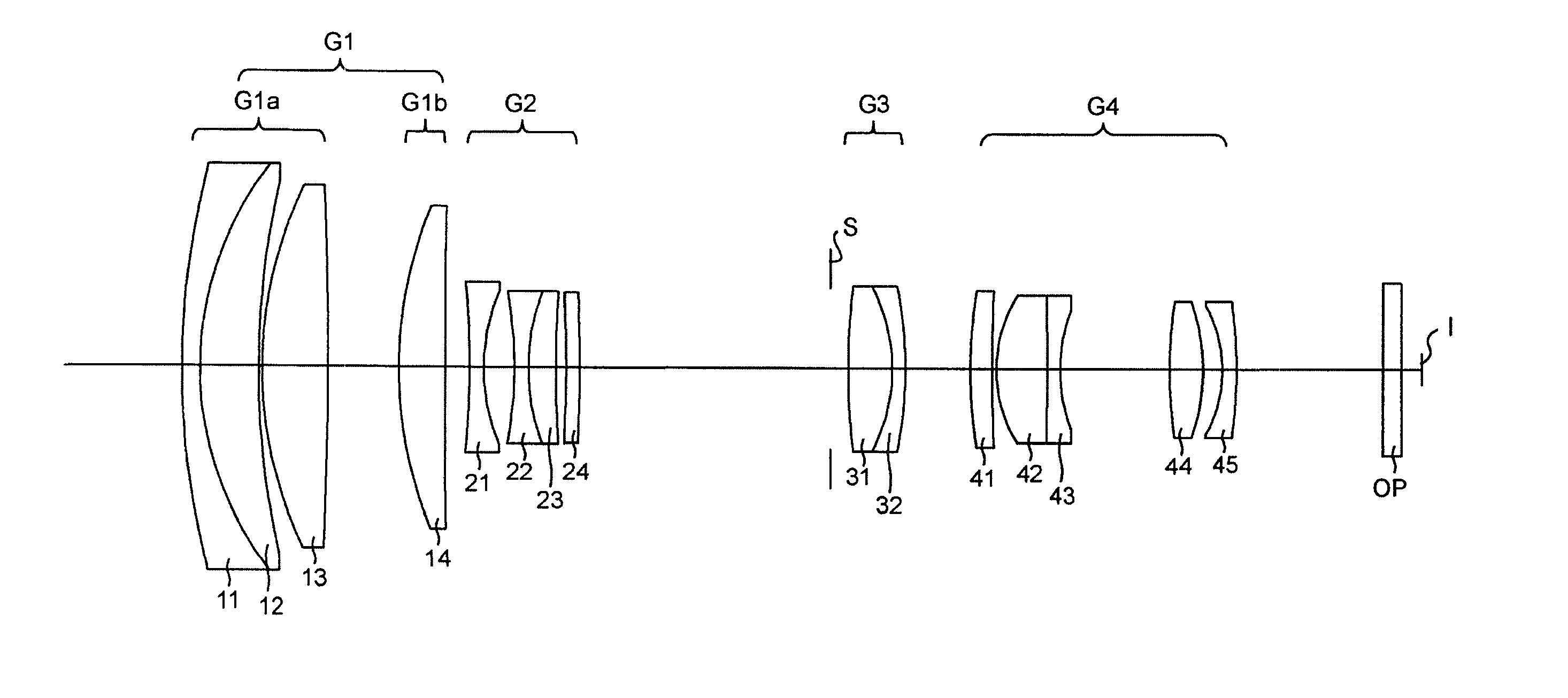
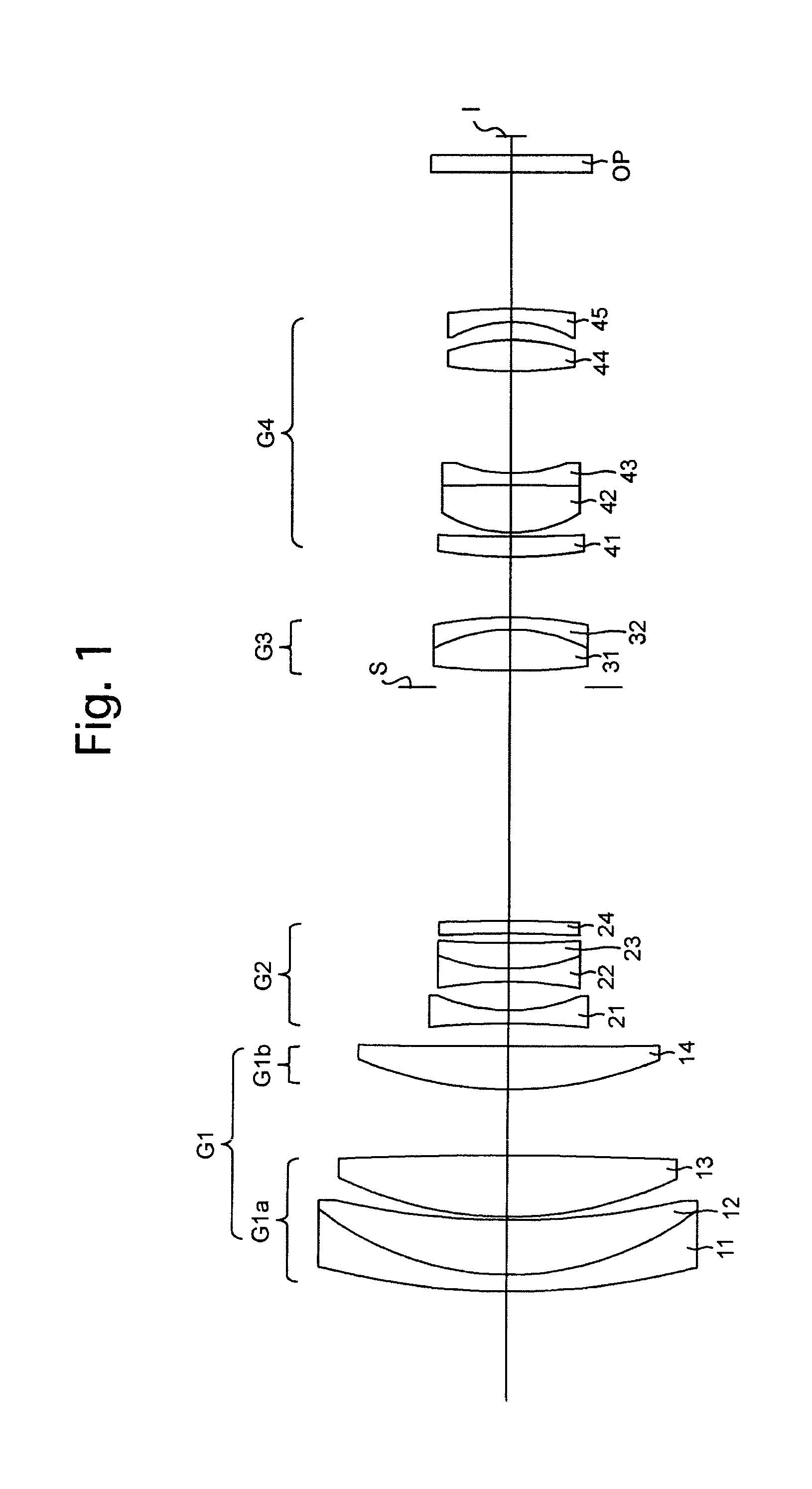
[0076]As shown in the zoom path of FIG. 43, the zoom lens system of the first embodiment is configured of a positive first lens group (specified lens group) G1, a negative second lens group G2, a positive third lens group G3, and a positive fourth lens group G4, in that order from the object side. The first lens group G1 is configured of a positive first sub-lens group G1a and a positive second sub-lens group (focusing lens group) G1b, in that order from the object side. A diaphragm S which is provided between the second lens group G2 and the third lens group G3 moves integrally with the third lens group G3 in the optical axis direction. “I” designates the image plane.

[0077]In the zoom lens system of the first embodiment, upon zooming from the short focal length extremity (Wide) to the long focal length extremity (Tele), the distance between the first lens group G1 and the second lens group G2 increases, the distance between the second lens group G2 and the third lens group G3 decre...

second embodiment

[0094]As shown in the zoom path of FIG. 45, the zoom lens system of the second embodiment is configured of a negative first lens group (specified lens group) G1′ and a positive second lens group G2′, in that order from the object side. The first lens group G1′ is configured of a negative first sub-lens group G1a′ and a positive second sub-lens group (focusing lens group) G1b′ in that order from the object side. A diaphragm S which is provided between the first lens group G1′ and the second lens group G2′ moves integrally with the second lens group G2 in the optical axis direction. “I” designates the image plane.

[0095]The zoom lens system of the second embodiment, upon zooming from the short focal length extremity (Wide) to the long focal length extremity (Tele), the distance between the first lens group G1′ and the second lens group G2′ decreases. Upon zooming from the short focal length extremity to the long focal length extremity, the distance between the first sub-lens group G1a′...

numerical embodiment 1

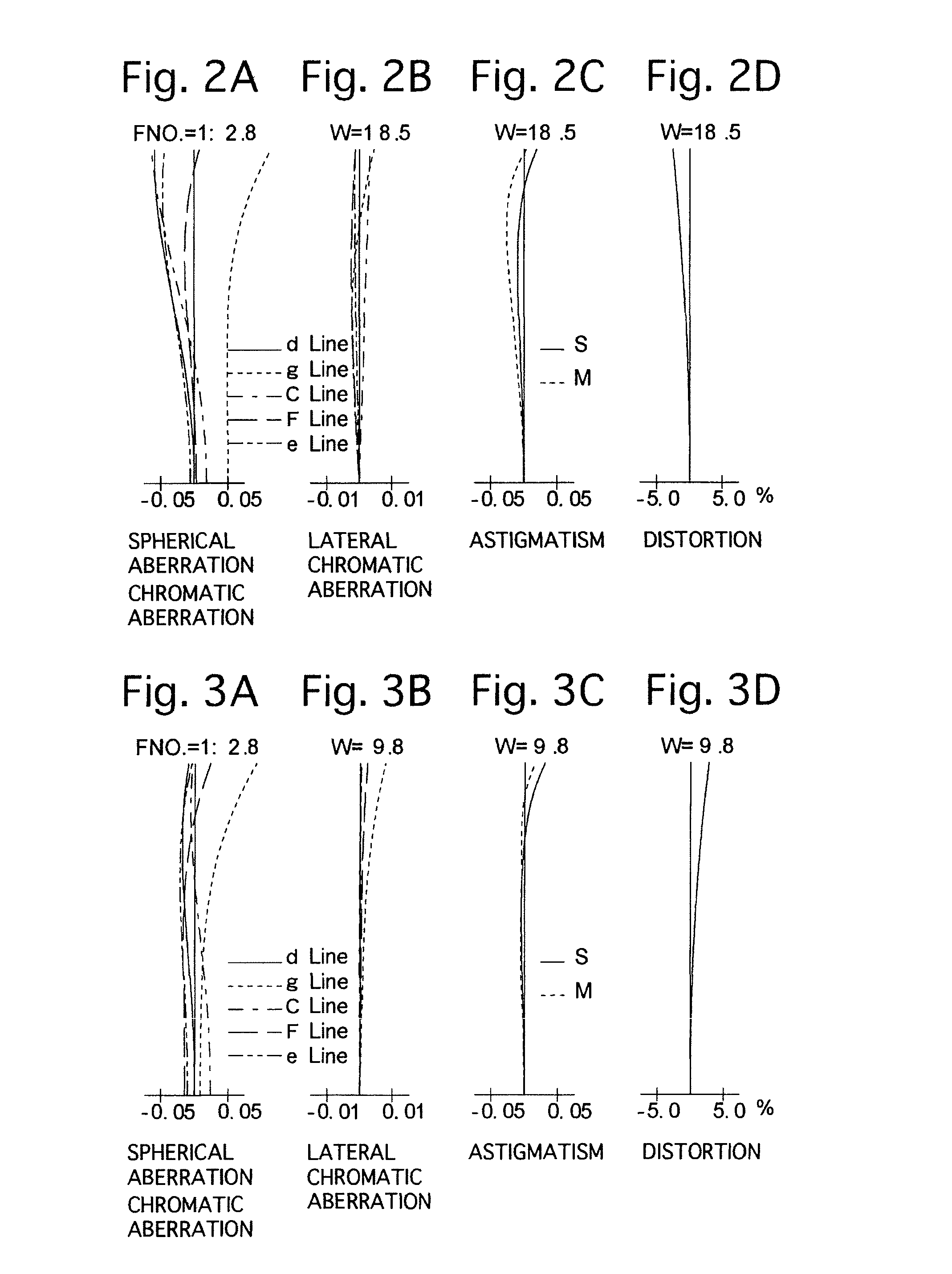
[0108]FIGS. 1 through 13D and Tables 1 through 6 show a first numerical embodiment according to the present invention. FIG. 1 shows a lens arrangement of the zoom lens system when focusing on an object at infinity at the short focal length extremity. FIGS. 2A, 2B, 2C and 2D show various aberrations that occurred in the zoom lens system of FIG. 1 at the short focal length extremity when focused on an object at infinity. FIGS. 3A, 3B, 3C and 3D show various aberrations that occurred in the lens arrangement shown in FIG. 1 at an intermediate focal length when focused on an object at infinity. FIGS. 4A, 4B, 4C and 4D show various aberrations that occurred in the lens arrangement shown in FIG. 1 at the long focal length extremity when focused on an object at infinity. FIGS. 5A, 5B, 5C and 5D show various aberrations that occurred in the zoom lens system of FIG. 1 at the short focal length extremity at a predetermined photographing distance (0.75 m) of a normal photography mode. FIGS. 6A,...


PUM


Abstract

A zoom lens system includes a plurality of lens groups, a lens group of which is moved to perform zooming, wherein a specified lens group of the lens groups is a focusing lens group; a normal photography mode in which focusing is carried out from infinity to a predetermined photographing distance by moving the focusing lens group of the specified lens group; and a shifting mode which shifts from the normal photography mode to a macro photography mode by moving a lens element of the specified lens group other than the focusing lens group when focusing on an object at a photographing distance that is shorter than the predetermined photographing distance. When the zoom lens system is in the macro photography mode, focusing is carried out from the predetermined photographing distance to a minimum photographing distance by moving the focusing lens group.

Description

BACKGROUND OF THE INVENTION[0001]1. Field of the Invention[0002]The present invention relates to a zoom lens system provided with a macro photographic function by which an object at an infinity through to an object at a close distance can be photographed.[0003]2. Description of Related Art[0004]In recent years, zoom lens systems which are provided with a macro photographic function, by which an object at an object-distance range from infinity through to a close-distance can be photographed, have become known to be used in electronic imaging devices such as digital cameras, etc. Such a type of zoom lens system demands miniaturization and weight-reduction of the focusing lens group thereof, demands a rapid and silent focusing operation, and are required to achieve a short minimum photographing distance.[0005]Japanese Patent No. 3,445,095, which discloses a zoom lens system having a positive first lens group, a negative second lens group, a negative third lens group and a positive four...

Claims


Application Information

Patent Timeline
Patent Type & Authority Applications(United States)
IPC IPC(8): G02B15/22
CPCG02B15/22G02B15/173G02B15/177G02B15/1425G02B15/20G02B15/144113G02B13/009G02B27/646G02B5/005G02B7/10G03B3/00G03B13/32G03B2205/0046G02B13/0045G02B15/163G02B13/18G02B9/34
Inventor ENOMOTO, TAKASHI
Owner RICOH IMAGING COMPANY
Why Eureka
Try Eureka