Shield connector

a shield connector and connector technology, applied in the direction of coupling device connection, coupling base/case, securing/insulating coupling contact member, etc., can solve the problem of trouble between the wire-side terminal and the device-side terminal, and achieve the effect of suppressing the vibration of the wire, simple construction and simple structur

Active Publication Date: 2014-05-01
SUMITOMO WIRING SYST LTD
View PDF9 Cites 43 Cited by
  • Summary
  • Abstract
  • Description
  • Claims
  • Application Information

AI Technical Summary

Benefits of technology

[0007]The invention is directed to a shield connector to be connected to a device-side connector provided on a device. The shield connector includes a housing and a terminal accommodated in the housing. The terminal is to be connected to a device-side terminal in the device-side connector. A wire is connected to the terminal and is pulled out of the housing. A shield shell covers the housing and is to be connected to a shield case of the device. A resin molded body is held in close contact with the outer peripheral surface of the wire and is sandwiched in a pull-out direction of the wire by a housing-side holding portion on the housing and a shell-side holding portion on the shield shell. This sandwiching of the resin molded body by the housing-side holding portion and the shell-side holding portion suppresses vibration of the wire in the pull-out direction caused by vibration of a vehicle or the like. The suppression of vibration of the wire in the housing prevents trouble between the terminal and the device-side terminal.
[0008]The housing may be formed with a wire pull-out hole from which the wire is pulled out from the interior of the housing and the housing-side holding portion may be an opening edge portion of the wire pull-out hole. Accordingly, the housing has a simple construction as compared with the case where the housing-side holding portion is provided separately on the inner side of the wire pull-out hole.
[0009]The resin molded body may fit into the wire pull-out hole. A housing-side seal ring may be mounted on the outer peripheral surface of the resin molded body for closely contacting the inner peripheral surface of the wire pull-out hole over the entire circumference. The housing-side seal ring provides sealing between the resin molded body and the inner peripheral surface of the wire pull-out hole and also functions as a shake suppressing portion for suppressing shaking of the resin molded body in the wire pull-out hole and for suppressing vibration of the wire in the pull-out direction due to the shaking of the resin molded body in the wire pull-out hole.
[0010]The shield shell may be formed to cover the resin molded body and the housing. A shell-side seal ring may be mounted on the outer peripheral surface of the resin molded body for closely contacting the outer peripheral surface of the resin molded body and the inner peripheral surface of the shield shell over the entire circumference. The shell-side seal ring provides sealing between the resin molded body and the shield shell and also functions as a shake suppressing portion for suppressing shaking of the resin molded body in the shield shell and suppressing vibration of the wire in the pull-out direction due to the shaking of the resin molded body in the shield shell.
[0011]The shield shell may be fixed to the shield case of the device by a bolt tightened in a direction intersecting with the pull-out direction of the wire. Thus, a fixing direction of the shield shell integral to the resin molded body intersects a vibration transmission direction for further suppressing vibration of the resin molded body.

Problems solved by technology

This vibration is transmitted to the wire-side terminal and may cause trouble between the wire-side terminal and the device-side terminal.

Method used


Image

  • Shield connector
  • Shield connector
  • Shield connector

Examples


Embodiment Construction

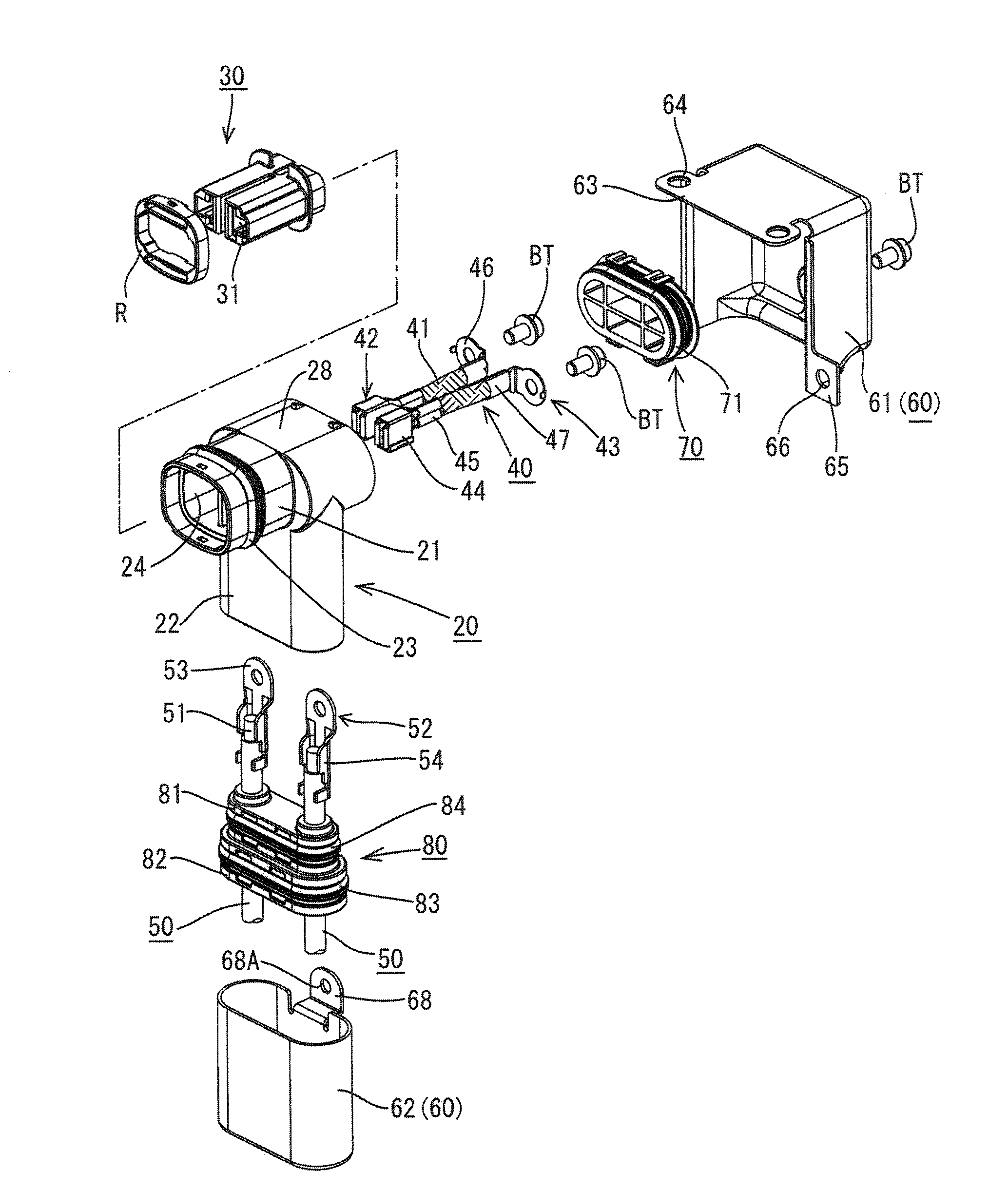
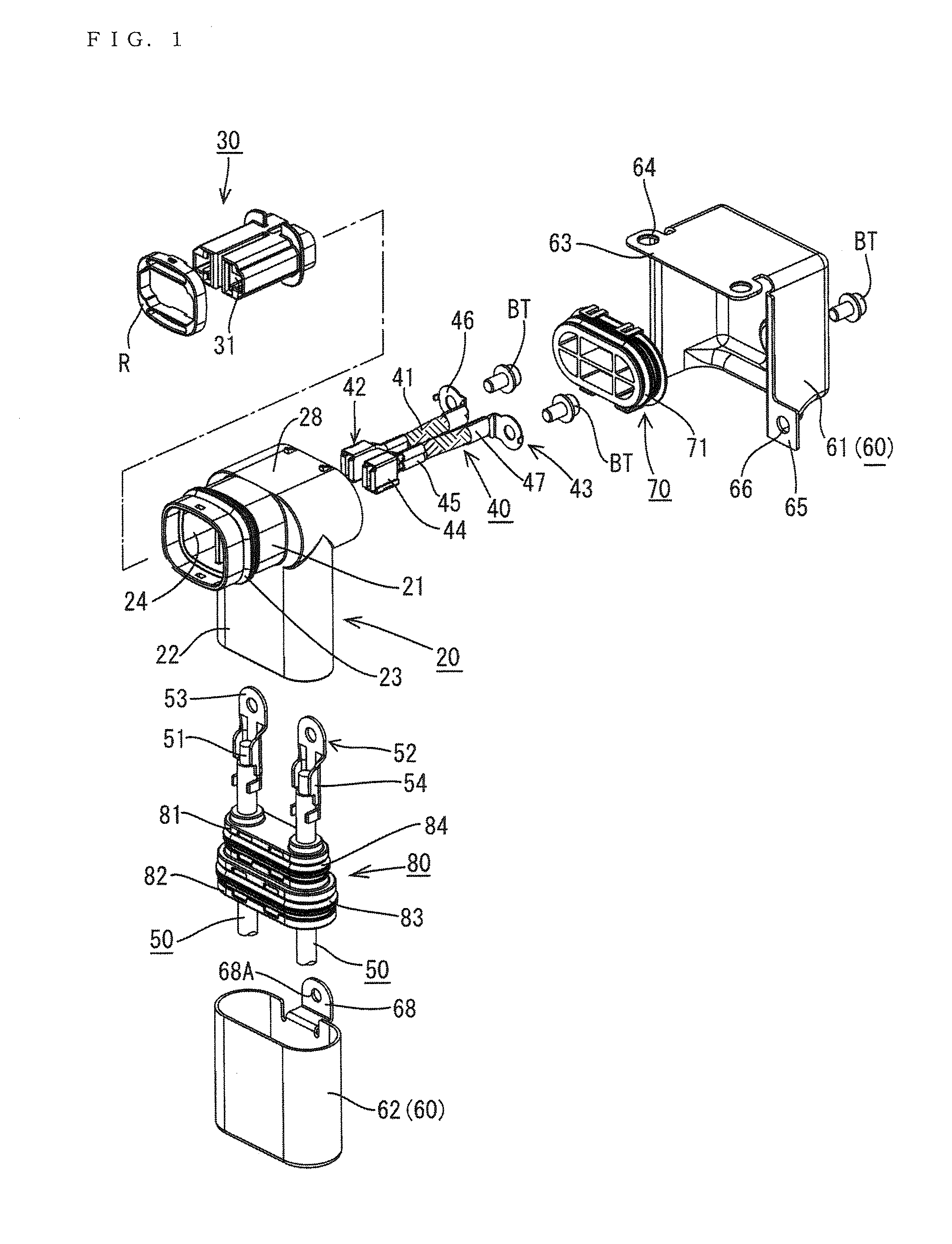
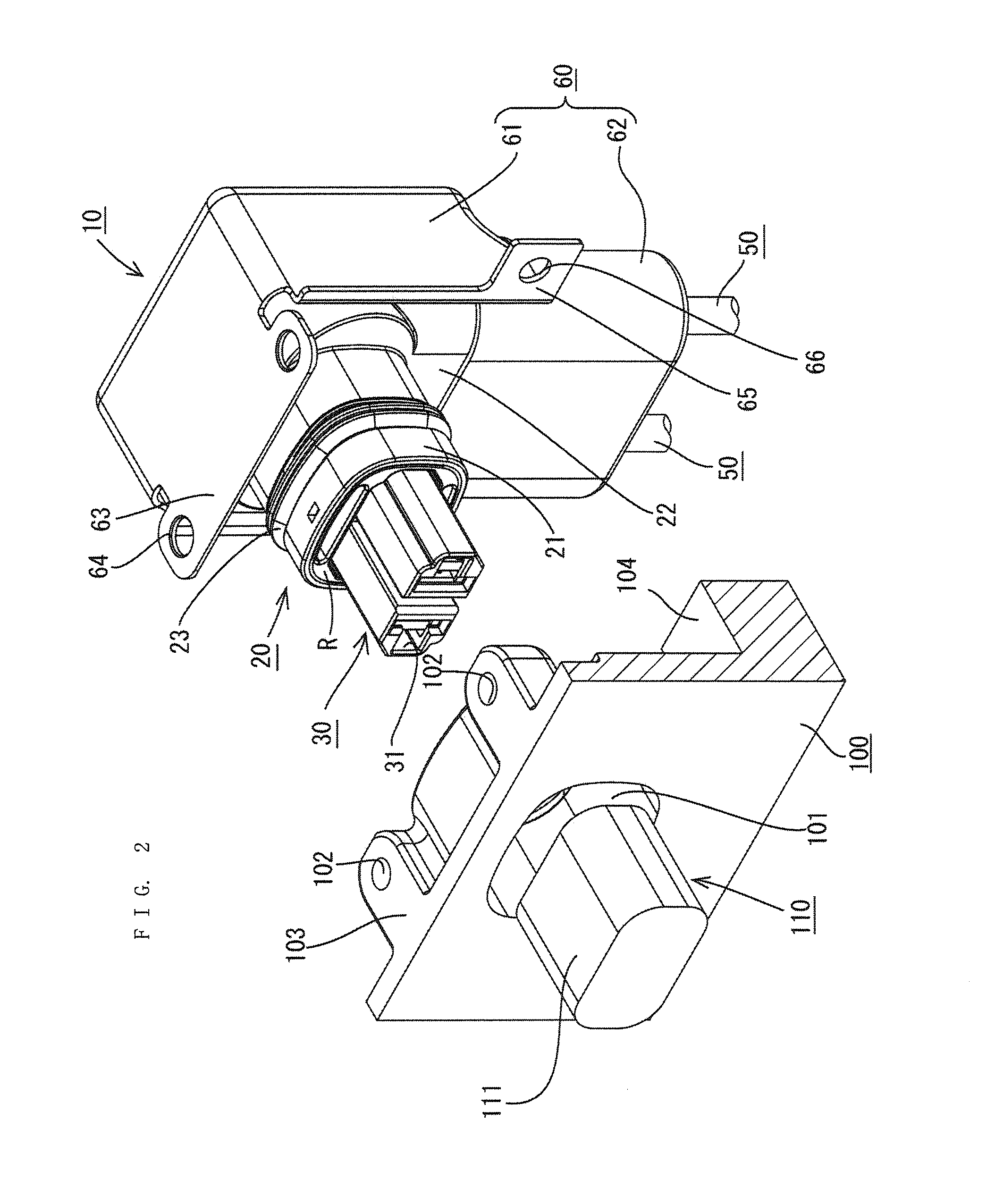
[0023]A shield connector in accordance with an embodiment of the invention is identified by the numeral 10 in FIG. 2. The shield connector 10 is to be mounted on a shield case 100 of a device (e.g. inverter, motor or the like of a vehicle such as a hybrid vehicle or an electric vehicle). As shown in FIG. 2, a device-side connector 110 connectable to the shield connector 10 is arranged at a position facing the shield connector 10 in a connecting direction in the shield case 100. Note that, in the following description, a vertical direction is based on that of FIG. 5 and a lateral direction is based on that of FIG. 5. Further, forward and backward directions are based on lateral directions of FIG. 6, wherein a leftward direction (connecting direction to the device-side connector 110) is referred to as a forward direction and a rightward direction (separating direction from the device-side connector 110) is referred to as a backward direction.

[0024]The device is such that a device main...


PUM


Abstract

A shield connector (10) to be connected to a device-side connector (110) provided on a device includes female terminals (42) to be connected to device-side terminals (112) provided in the device-side connector (110), a housing main body (20) including a wire pull-out hole (25) from which outer wires (50) connected to the female terminals (42) are pulled out, a shield shell (60) to be connected to a shield case (100) of the device while covering the housing main body (20), and a resin molded body (80) held in close contact with the outer peripheral surfaces of the outer wires (50). The resin molded body (80) is vertically sandwiched by an opening edge portion (25A) of the wire pull-out hole (25) in the housing main body (20) and a shell-side holding portion (67) provided on the shield shell (60).

Description

BACKGROUND[0001]1. Field of the Invention[0002]The invention relates to a shield connector.[0003]2. Description of the Related Art[0004]U.S. Patent Application Publication No. 2012 / 0100753 discloses a shield connector with a wire-side terminal connected to an end of a wire. The wire-side terminal is accommodated in a housing that can be connected to a device-side connector in a device so that the wire-side terminal connects to a device-side terminal in the device-side connector. A shield shell covers the housing and has a lower opening. T the wire-side terminal is inserted through the lower opening of the shield shell and into the housing. A rubber plug seals the lower opening of the shield shell and is retained by a holder to prevent water from entering the shield shell.[0005]Clearances are provided between the shield shell and the holder and between the holder and the wire to permit efficient assembly. Thus, the holder is assembled loosely with the wire and the shield shell. The l...

Claims


Application Information

Patent Timeline
Patent Type & Authority Applications(United States)
IPC IPC(8): H01R13/52
CPCH01R13/5202H01R13/6581H01R13/5208H01R13/6593H01R2103/00
Inventor ITSUKI, KIYOTAKAMATSUOKA, HIROYUKIKASHIWADA, TOMOKAZU
Owner SUMITOMO WIRING SYST LTD
Why Eureka
Try Eureka