Air conditioning register

a technology for air conditioners and registers, applied in lighting and heating apparatus, ventilation systems, heating types, etc., can solve the problems of increasing pressure loss and/or noise generation, increasing etc., and reducing operating load and reducing pressure loss and noise generation.

Active Publication Date: 2014-05-01
TOYODA GOSEI CO LTD
View PDF24 Cites 20 Cited by
  • Summary
  • Abstract
  • Description
  • Claims
  • Application Information

AI Technical Summary

Benefits of technology

[0015]Accordingly, it is an objective of the present invention to provide an air conditioning register with reduced pressure loss and noise generation in which with upstream fins, a ventilation passage can be closed with a reduced operating load on an operation knob.

Problems solved by technology

Such an air conditioning register that uses a rack and a pinion as disclosed in Japanese Patent No. 4055693 causes problems of bringing about an increase in pressure loss and / or generation of noise.
The rack, which thus has a great dimension in both the face width direction (in the thickness direction of the downstream fins) and the teeth arrangement direction (in the axial direction of the downstream fin shafts), and accordingly has a high ventilation resistance, resulting in an increase in pressure loss and generation of noise.

Method used


Image

  • Air conditioning register
  • Air conditioning register
  • Air conditioning register

Examples


first embodiment

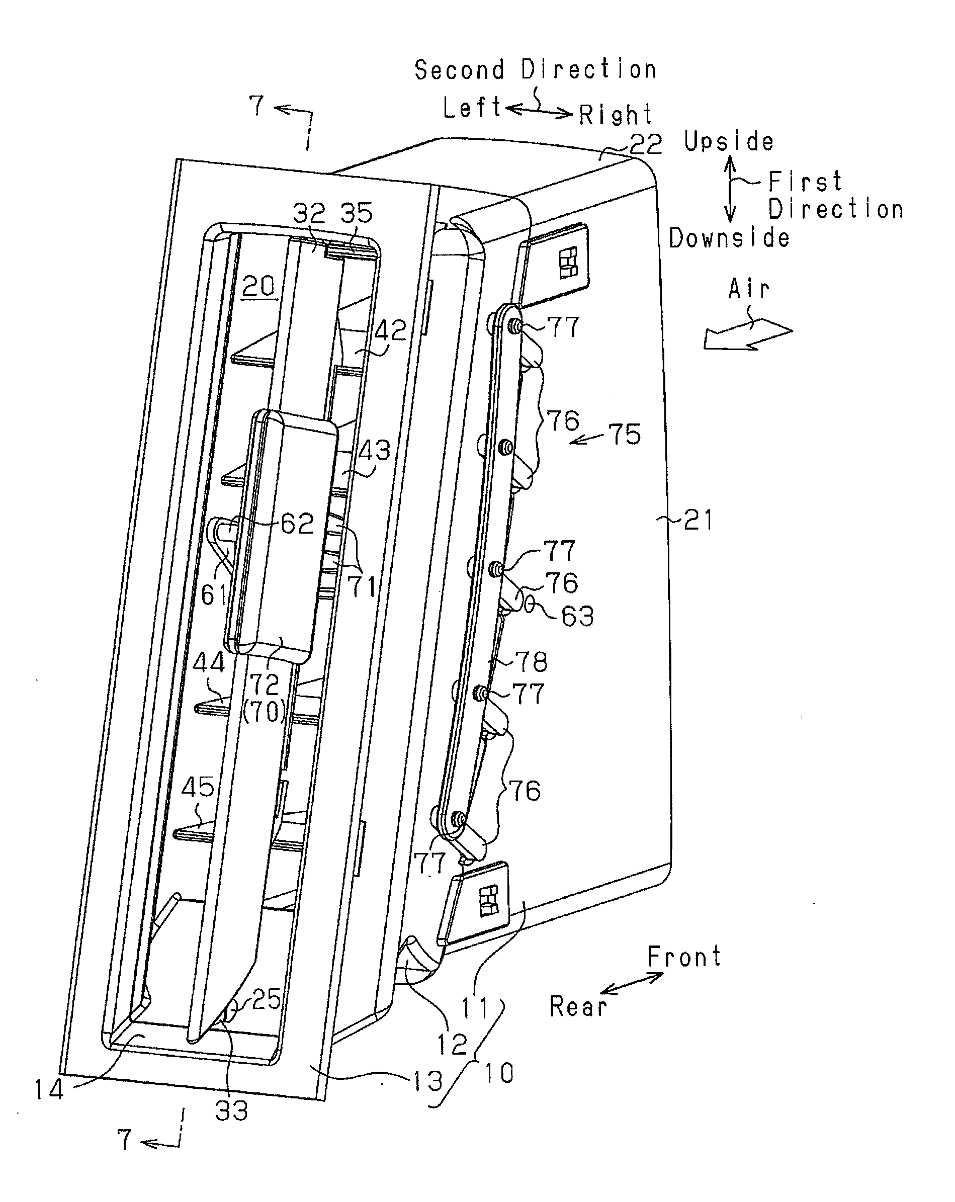
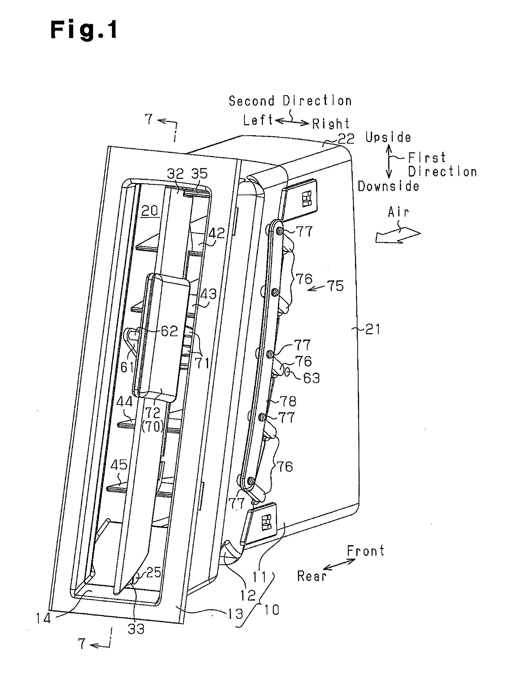
[0050]An air conditioning register according to a first embodiment will hereinafter be described with reference to FIGS. 1 to 22. The air conditioning register is for use in a vehicle. The air conditioning register has a thin structure with the horizontal dimension being smaller than the vertical dimension.

[0051]In the description below, the traveling direction (direction of forward movement), the direction of rearward movement, and the height direction of the vehicle are defined, respectively, as front, rear, and vertical. The right and left in the width direction (lateral direction) of the vehicle are also defined based on the direction of forward movement of the vehicle.

[0052]In the passenger compartment, an instrument panel is provided in front of the vehicle front seats (the driver seat and the front passenger seat). Air conditioning registers are assembled in, for example, a central portion and side portions of the instrument panel in the vehicle width direction. Like normal a...

second embodiment

[0140]Next will be described an air conditioning register according to a second embodiment with reference to FIGS. 23 to 30. The description will focus on components of the air conditioning register different from those in the first embodiment.

10>

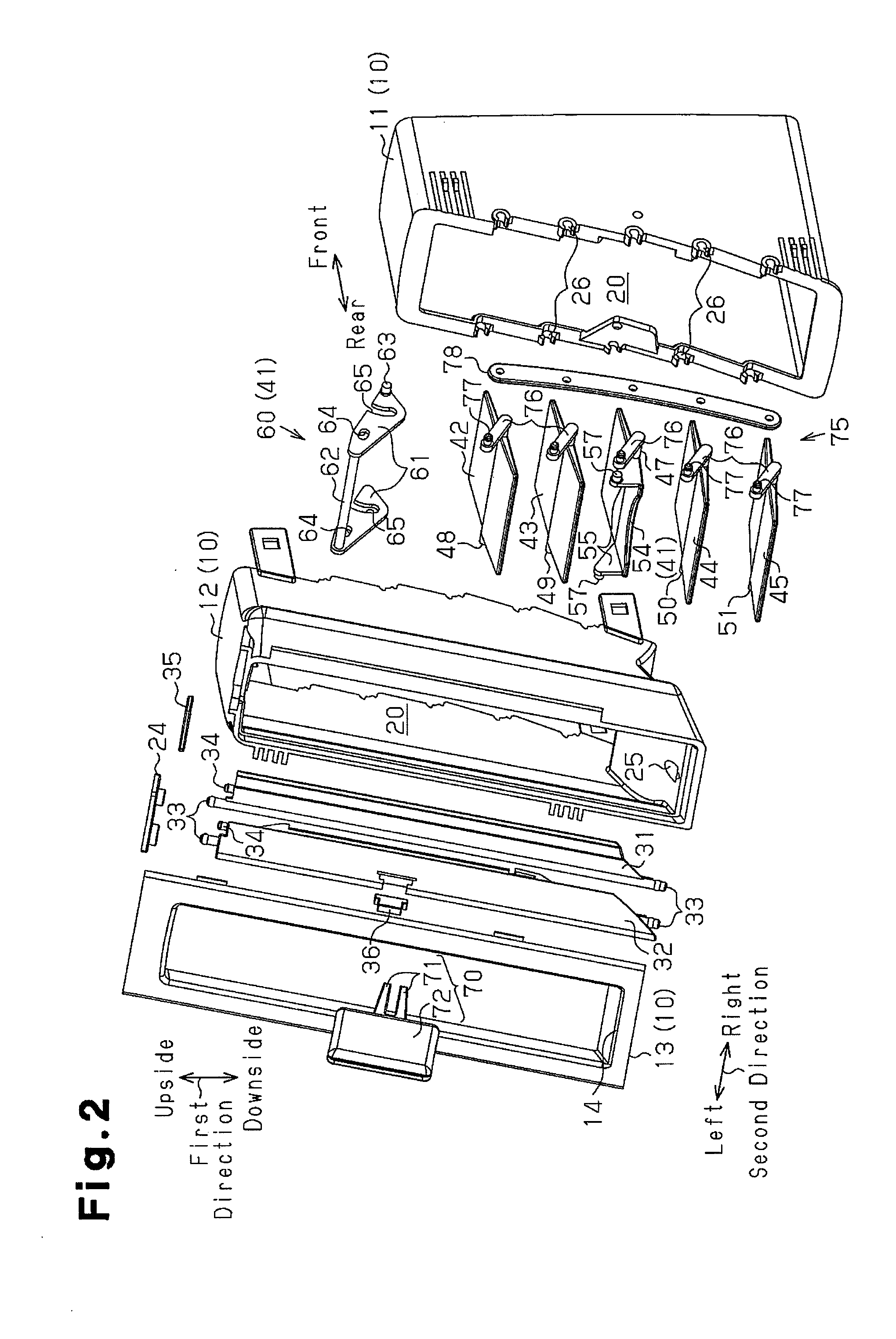
[0141]As shown in FIGS. 23 and 24, the case 10 includes the upstream retainer 11 and the downstream retainer 12. The bezel 13 having the outlet port 14 is formed integrally with the downstream retainer 12. Unlike the first embodiment, the dimensions of the outlet port 14 in the first direction (vertical direction) and in the second direction (lateral direction) are substantially the same.

[0142]The group of downstream fins includes the multiple downstream fins 31 and 32 each formed in an elongated plate shape longer in the second direction than in the direction of airflow. In this second embodiment, the number of the downstream fins 31 and 32 of the group is greater than that in the first embodiment. Among the multiple downstream fins 31 and...


PUM


Abstract

An air conditioning register is provided that includes a case, a downstream fin, a specific upstream fin extending in a direction perpendicular to the downstream fin, and an operation knob. The specific upstream fin includes a fin main body pivotally supported by the case via an upstream fin shaft and a transmission body pivotally supported by the case via a pivot located further upstream than the upstream fin shaft. The fin main body and the transmission body are coupled to each other. The operation knob is mounted slidably on the downstream fin and includes a pair of fork portions sandwiching a transmission shaft portion of the transmission body therebetween. When the operation knob is operated to slide and thereby the transmission shaft portion is moved, the fin main body of the specific upstream fin is tilted.

Description

BACKGROUND OF THE INVENTION[0001]The present invention relates to an air conditioning register in which fins are used to adjust the direction of flow of air conditioning air fed from an air conditioner to be blown into a compartment and, more particularly, to an air conditioning register having a structure in which fins are used to selectively open and close a ventilation passage.[0002]Japanese Patent No. 4055693, for example, discloses an air conditioning register for adjusting the direction of flow of air conditioning air fed from an air conditioner to be blown into a passenger compartment, the register having a structure in which fins are used to close a ventilation passage.[0003]The air conditioning register includes a case, multiple downstream fins, multiple upstream fins, and an operation knob. The downstream fins are each pivotally supported by the case via a downstream fin shaft. The upstream fins are located upstream of the downstream fins and extend in a direction perpendi...

Claims


Application Information

Patent Timeline
Patent Type & Authority Applications(United States)
IPC IPC(8): F24F13/14F24F13/15
CPCF24F13/1426F24F13/15F24F13/075B60H1/3421B60H2001/3471
Inventor TAKAI, HAJIMEOGURA, MITSUOSHIBATA, MINORUASANO, KENJI
Owner TOYODA GOSEI CO LTD
Why Eureka
Try Eureka