

Bone joint replacement and repair assembly and method of repairing and replacing a bone joint
a bone joint and joint technology, applied in the field of bone joint replacement and repair assembly, can solve the problems of rotator cuff, easy damage to the rotator cuff, and difficult process of inserting implants and replacing pivotal bone joints,
- Summary
- Abstract
- Description
- Claims
- Application Information
AI Technical Summary
Benefits of technology
Problems solved by technology
Method used
Image

Examples
Embodiment Construction
[0002]1. Field of the Invention
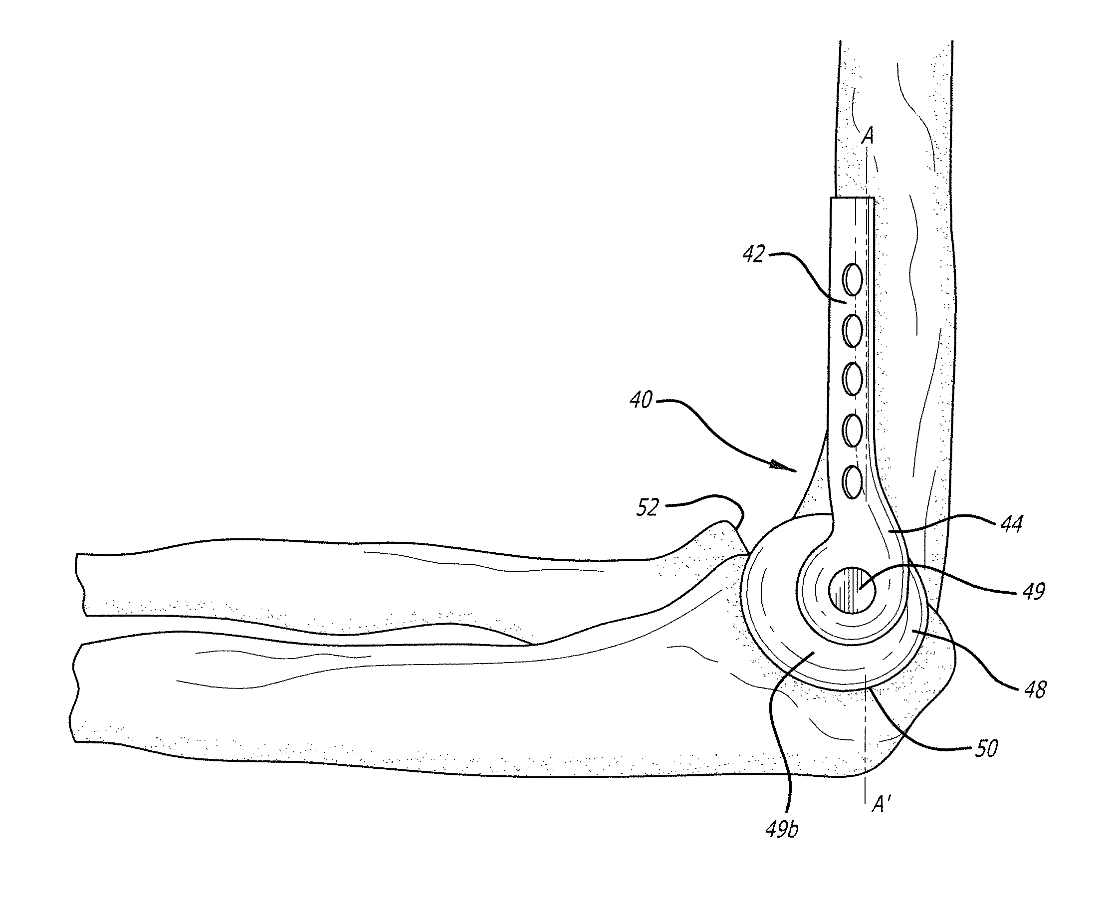
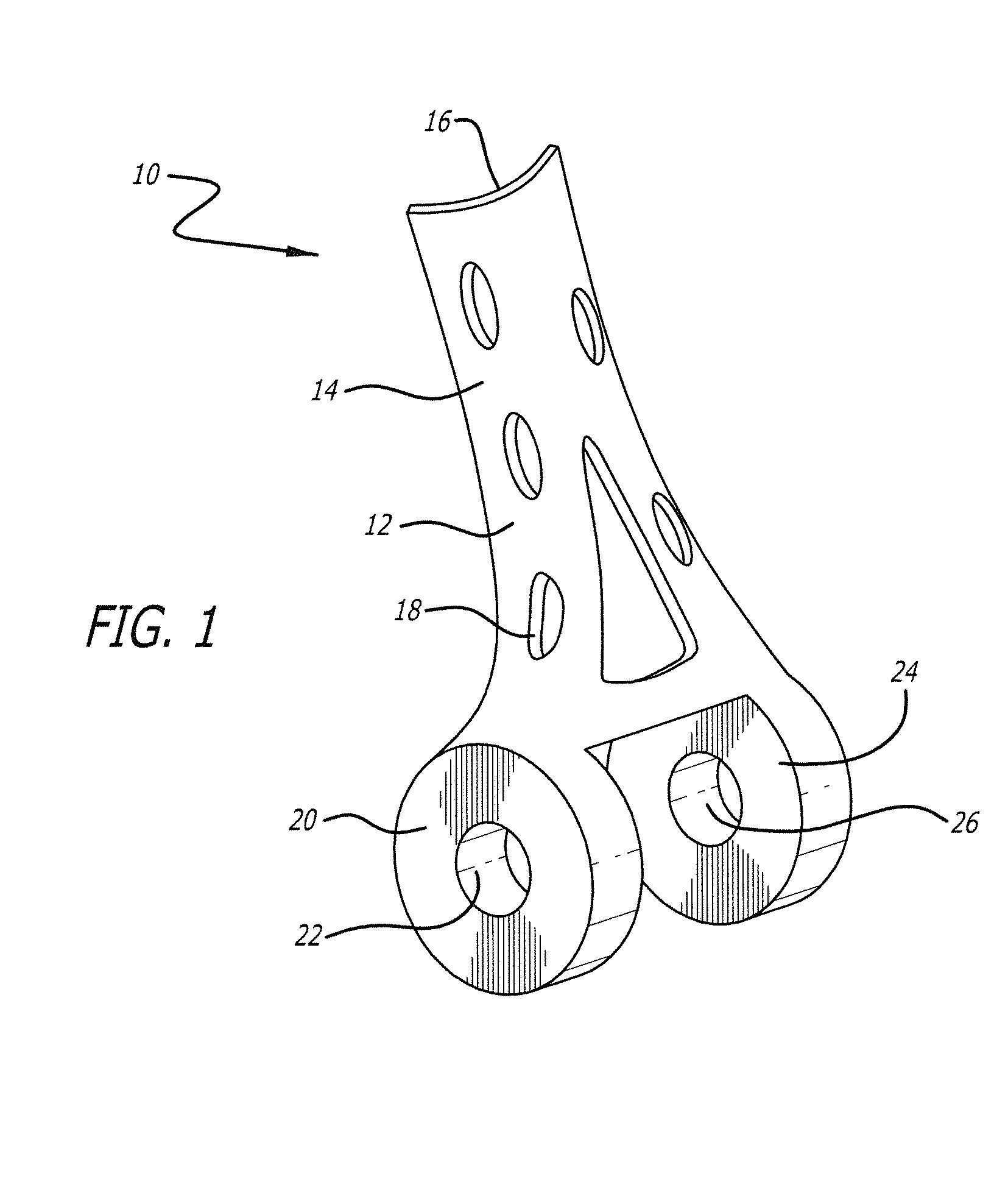
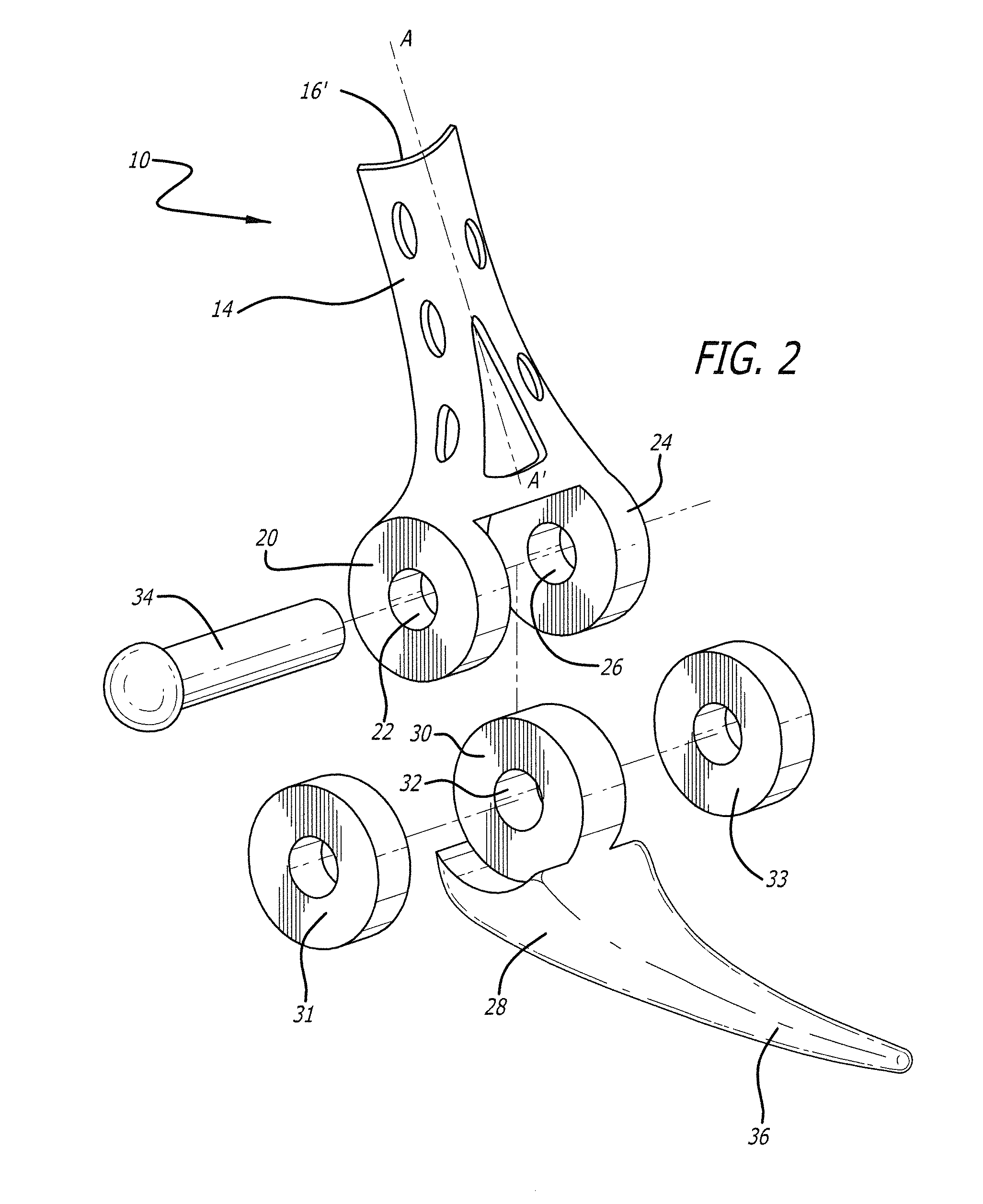
[0003]The present invention broadly relates to assemblies used in the repair and replacement of pivotal bone joints. More particularly, the present invention relates to assemblies for replacement and partial replacement of elbows, joint repair implants for other relatively small pivotal joints such as wrists, ankles, and knees, repair of fractured bone heads proximate joints, and implants for repair of shoulder rotator cuff injuries.
[0004]2. BACKGROUND OF THE INVENTION
[0005]Inserting implants and replacing pivotal bone joints, particularly relatively small joints such as elbows, wrists, ankles, and knees, is a difficult process due to the relatively complex configuration of such joints. While all pivotal bone joints are defined by an intersection and cooperation of proximal and distal heads of different bones, held together by a plurality of ligaments, relatively smaller pivotal joints, such as elbows, wrists, ankles, and knees have a large number of b...
PUM
 Abstract
Description
Claims
Application Information