Torque converter stator structure

a technology of torque converter and stator, which is applied in the direction of rotary clutches, fluid couplings, gearing, etc., can solve the problem of low capacity coefficient in the high speed ratio region, achieve effective alignment, increase the chord length of the blade, and enhance the effect of aligning the flow of oil

Active Publication Date: 2014-05-08
HONDA MOTOR CO LTD +1
View PDF0 Cites 4 Cited by
  • Summary
  • Abstract
  • Description
  • Claims
  • Application Information

AI Technical Summary

Benefits of technology

[0015]In accordance with the first aspect of the present invention, in a region where the speed ratio of the torque converter is small, the first and second one-way clutches are both engaged, the first and second stators are both restrained on the fixed part, and oil flows along the blades of the first and second stators and its flow is aligned in a desired direction. When the direction of flow of oil entering the stator changes accompanying an increase in the speed ratio, since the first one-way clutch is disengaged and the first stator idles to thus prevent the speed of the first stator blade from decreasing, oil flows along the second stator blade of the second stator and the flow is aligned in a desired direction. In a region where the speed ratio is large, since the direction of flow of oil entering the stator further changes, the first and second one-way clutches are both disengaged, the first and second stators both idle, and oil can flow out in a desired direction without interference from the first and second stator blades.
[0016]Since, of the first and second stators, the number of blades of one stator is larger than the number of blades of the other stator, and the maximum value for the blade thickness of the blade of the one stator is smaller than the minimum value for the blade thickness of the blade of the other stator, it is possible to ensure that there is a sufficient gap between the trailing edge of the first stator blade and the leading edge of the second stator blade, thus preventing the flow of oil from being stopped by the gap, and it is possible to align effectively the flow of oil by means of the stator blades of the one stator, which are larger in number, thereby achieving a balance between improvement of the torque ratio and improvement of the capacity coefficient of the torque converter.
[0017]Furthermore, in accordance with the second aspect of the present invention, since the length in the axial direction of the radially outer end part of the blade of the one stator is larger than the length in the axial direction of the radially inner end part of the blade, it is possible to enhance the effect in aligning the flow of oil by increasing the chord length of the blade.
[0018]Moreover, in accordance with the third aspect of the present invention, since the blade of the one stator is made by metal plate pressing, it can be produced at low cost. Furthermore, although the blade of the other stator is made by die-casting, since the stator is divided into two, compared with a case in which it is not divided, warpage of the blade of the other stator becomes smaller, and the structure of a mold can be simplified, thus cutting the production cost.

Problems solved by technology

The high torque ratio type torque converter has an excellent torque ratio in a low speed ratio region compared with the high capacity type torque converter, but there is the problem that the capacity coefficient in a high speed ratio region is still low.

Method used


Image

  • Torque converter stator structure
  • Torque converter stator structure
  • Torque converter stator structure

Examples


first embodiment

[0047]A first embodiment of the present invention is now explained by reference to FIG. 1 to FIG. 5.

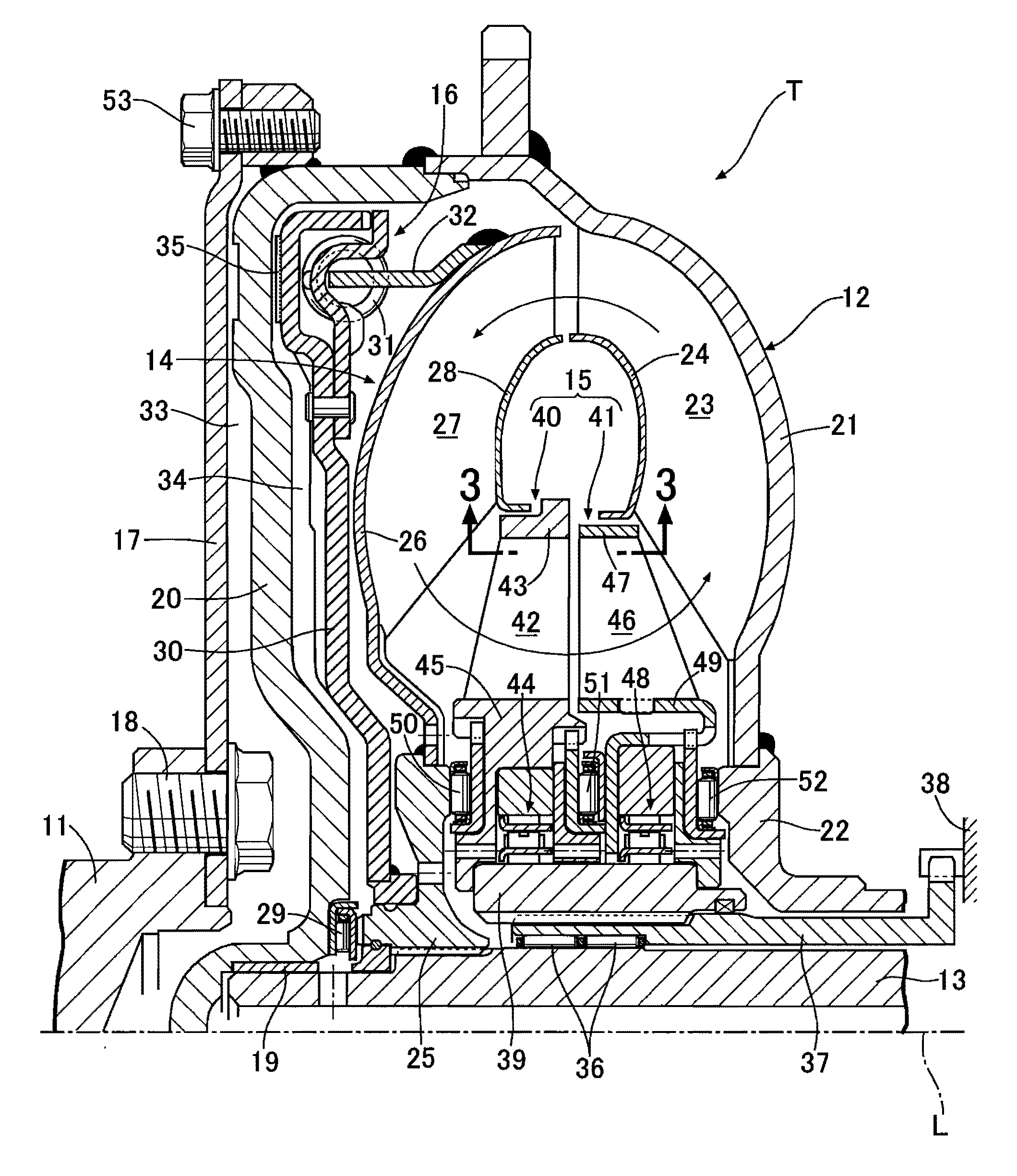
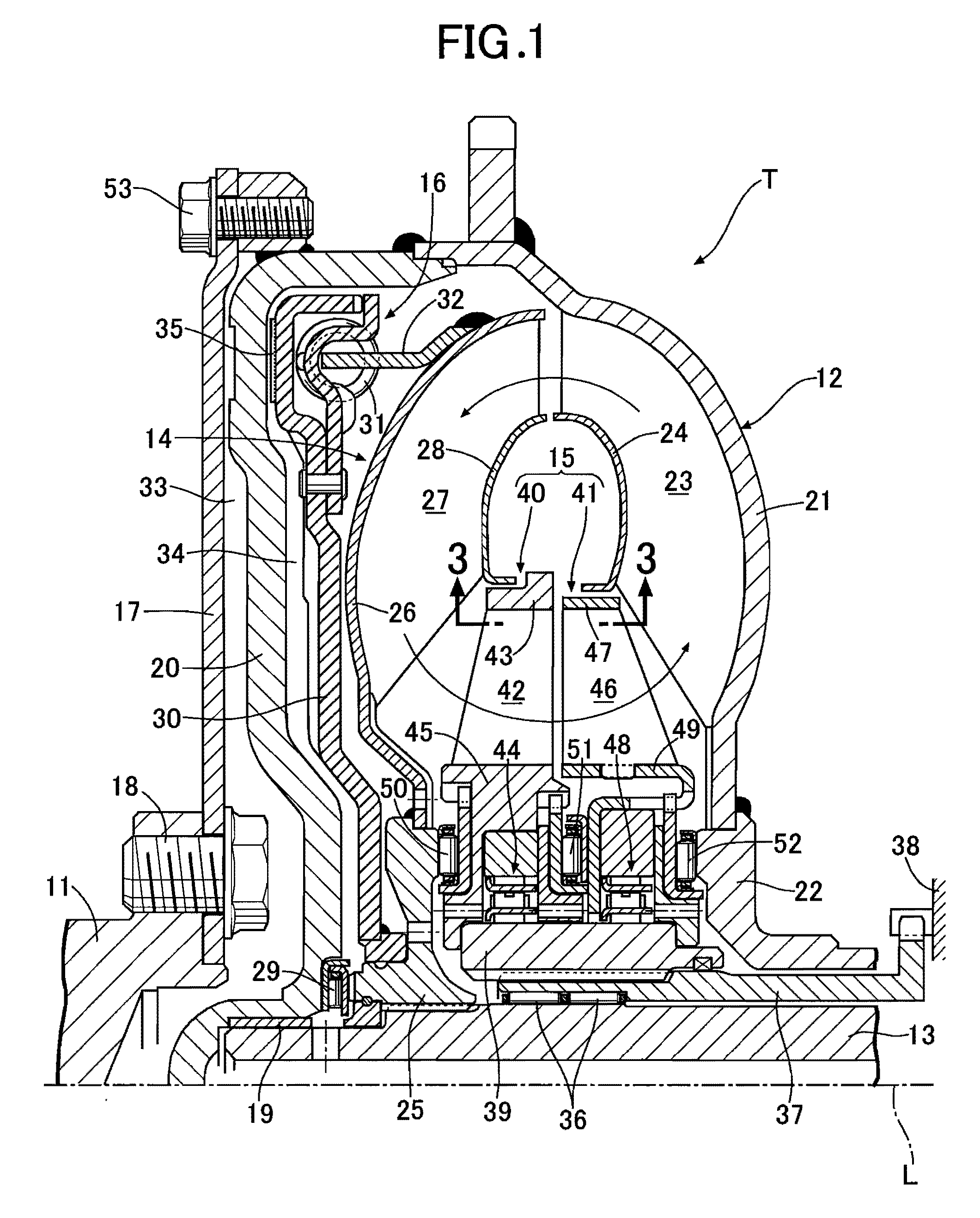
[0048]As shown in FIG. 1, a torque converter T for an automobile includes a pump impeller 12 that is connected to a crankshaft 11 of an engine (not illustrated) as a drive source, a turbine runner 14 that is connected to a main shaft 13 of a transmission (not illustrated), a stator 15 disposed between the pump impeller 12 and the turbine runner 14, and a lockup clutch 16 that can join the pump impeller 12 and the turbine runner 14. The crankshaft 11 and the main shaft 13 are coaxially disposed on an axis L of the torque converter T in a state in which shaft ends thereof oppose each other.

[0049]A plate-shaped drive plate 17 is fixed to the shaft end of the crankshaft 11 by means of bolts 18, and an outer peripheral part of the drive plate 17 is fixed, by means of bolts 53, to an outer peripheral part of a bowl-shaped torque converter cover 20 rotatably supported on the shaft end of the...

second embodiment

[0072]A second embodiment of the present invention is now explained by reference to FIG. 6 to FIG. 8.

[0073]The second embodiment is different from the first embodiment in terms of the shape of second stator blades 46 of a second stator 41, the arrangement otherwise being the same as that of the first embodiment.

[0074]With regard to the second stator blades 46 of the second embodiment, a chord length L2 of a radially outer side portion is larger than a chord length L1 of a radially inner side portion. This enables the flow of oil to be aligned by means of the second stator blades 46 more effectively. If an attempt were to be made to produce the second stator blades 46 with such a shape by die casting, since it would be difficult to carry out release from a mold, the structure of the mold would become complicated, but they can easily be produced by metal plate pressing.

third embodiment

[0075]A third embodiment of the present invention is now explained by reference to FIG. 9 to FIG. 13.

[0076]In the first embodiment, the first stator blades 42 of the first stator 40 have a complete airfoil that has a large blade thickness, and the second stator blades 46 of the second stator 41 have a flat plate-shaped airfoil that has a very small blade thickness, but in the third embodiment the relationship is reversed.

[0077]That is, with regard to a first stator 40, a first stator core 43, a first stator boss 45, and first stator blades 42 are produced separately by press forming a metal plate and they are assembled as a unit by welding. Therefore, the airfoil formed from a leading edge 42a, a trailing edge 42b, a ventral surface 42c, and a dorsal surface 42d of the first stator blade 42 has a flat plate shape having a constant blade thickness that is equal to the plate thickness of the metal plate.

[0078]On the other hand, a second stator 41 is a member that is made by die-castin...


PUM

PropertyMeasurementUnit
thicknessaaaaaaaaaa
lengthaaaaaaaaaa
torque ratioaaaaaaaaaa

Abstract

Among first and second stators of a torque converter supported on a fixed part by a one-way clutch corresponding to the stators, the number of second stator blades of the second stator on the downstream side in the direction of flow of oil is larger than the number of first blades of the first stator on the upstream side, and the maximum value t2 for blade thickness of the second stator blade is smaller than the minimum value t1 for blade thickness of the first stator blade. Therefore, it is possible to ensure that there is a sufficient gap (β) between a trailing edge of the first stator blade and a leading edge of the second stator blade, thus preventing the flow of oil from being stopped by the gap (β), and it is possible to align effectively the flow of oil by means of the second stator blades.

Description

TECHNICAL FIELD[0001]The present invention relates to a torque converter stator structure that includes a pump impeller that is connected to a drive source and rotates around an axis, a turbine runner that is connected to an input shaft of a transmission and rotates around the axis, and a stator that is disposed between the pump impeller and the turbine runner, the stator including a first stator that is positioned on an upstream side in a direction of circulation of oil and a second stator that is positioned on a downstream side in the direction of circulation, and the first and second stators being supported on a fixed part via corresponding one-way clutches.BACKGROUND ART[0002]A torque converter for an automobile includes a pump impeller connected to a crankshaft of an engine, a turbine runner connected to a main shaft of a transmission, and a stator supported on a casing via a one-way clutch, drives the turbine runner by means of a flow of oil generated by the pump impeller, and...

Claims


Application Information

Patent Timeline
Patent Type & Authority Applications(United States)
IPC IPC(8): F16H41/26F16H41/28
CPCF16H41/28F16H41/26F16H45/02F16H2041/246F16H2041/285F16H61/60
Inventor OKAJI, TOMOYAABE, HIROYAMISHIMA, YOSHITAKAUSUI, TOMOHIKOKITAJIMA, AKIRATSUCHIYA, TOMOHIKO
Owner HONDA MOTOR CO LTD
Why Eureka
Try Eureka