Blast shield

a shield and shield technology, applied in the field of shields, can solve the problems of limiting many design options, improvised explosive devices (ieds) also pose a significant risk, and many military and civilian endeavors are subject to the risks of encountering an explosion from unexploded ordnance, so as to achieve the effect of discharging the momentum of explosive for

Inactive Publication Date: 2014-05-08
MEGGITT ROCKMART
View PDF4 Cites 18 Cited by
  • Summary
  • Abstract
  • Description
  • Claims
  • Application Information

AI Technical Summary

Benefits of technology

[0006]In a first embodiment, the present invention provides a blast shield placed over a structure to be protected from the force of a blast. The blast shield comprises a support assembly and a plurality of first deflection members secured to said support assembly, each of said plurality of first deflection members presenting opposed surfaces angling away from the direction of an incoming explosive force, such that an incoming explosive force is split and deflected by the opposed surfaces thus dissipating the momentum of the explosive force.

Problems solved by technology

It is an unfortunate fact that many military and civilian endeavors are subject to the risks of encountering an explosion from unexploded ordnance (UXO) and other munitions and explosives of concern (MEC).
In particular military operations improvised explosive devices (IEDs) also pose a significant risk.
This limits many design options, as many vehicles cannot efficiently and practically bear the additional weight.
As another disadvantage, the V-hull designs are not readily retrofit to existing vehicles.

Method used


Image

  • Blast shield
  • Blast shield

Examples


Embodiment Construction

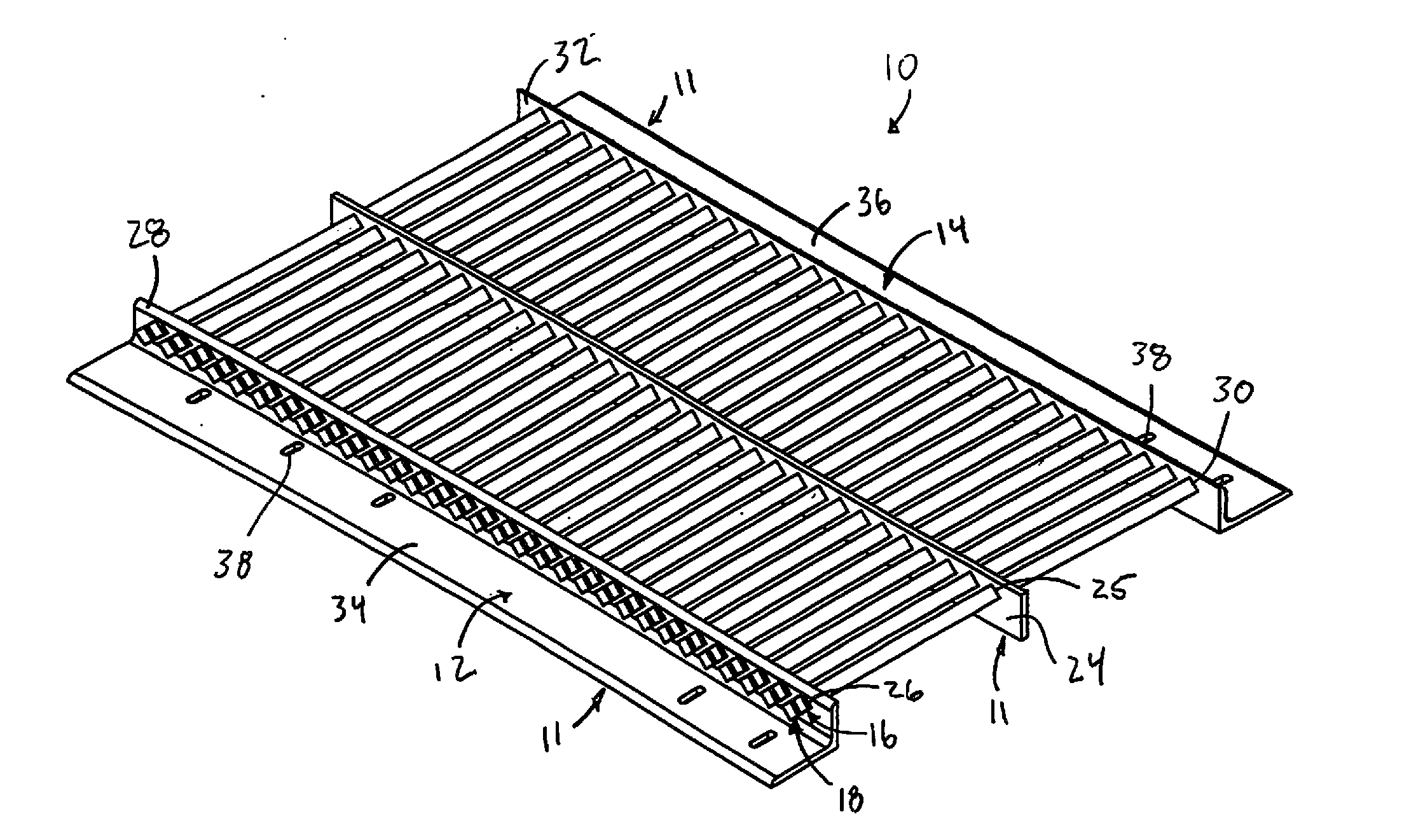
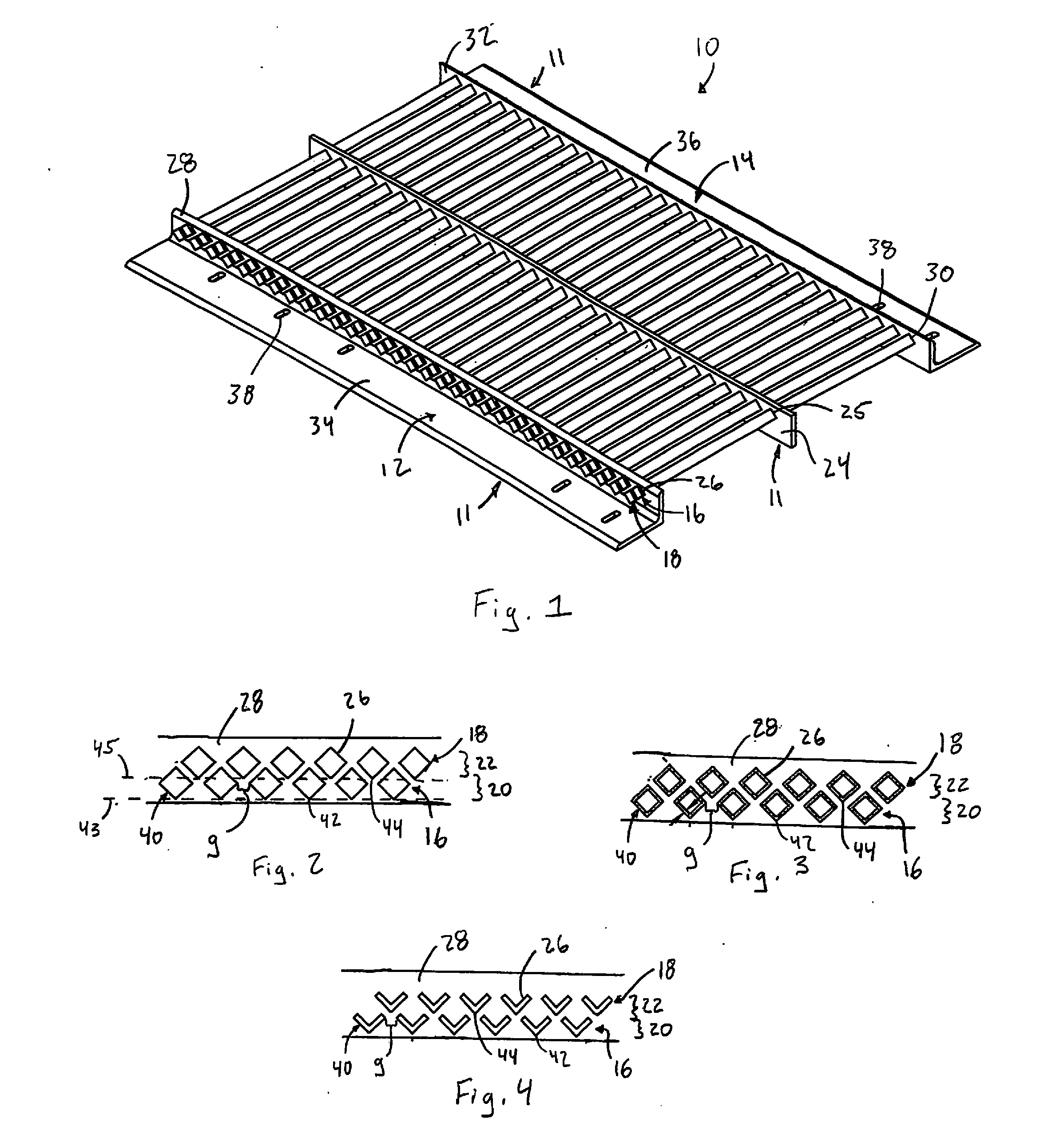
[0027]Referring now to FIG. 1, a blast shield in accordance with this invention is shown and designated by the numeral 10. The blast shield 10 includes a support assembly 11, including a first side support 12 and an opposed second side support 14 and a one or more optional intermediate supports such as intermediate support 24. The first side support 12 and the second side support 14 extend in a longitudinal direction, and a multitude of deflection members extend transversely between them. More particular, a plurality of first deflection members 16 extend transversely from a sidewall (or web) 28 of the first side support 12 to a sidewall (or web) 32 the second side support 14, and a plurality of second deflection members 18 extend perpendicularly from the sidewall 28 of the first side support 12 to the sidewall 32 of the second side support 14. The deflection members 16, 18 may instead extend obliquely to the first and second side supports 12, 14. The plurality of first deflection me...


PUM


Abstract

A blast shield placed over a structure to be protected from the force of a blast includes a support assembly and a plurality of first deflection members secured to said support assembly. Each of said plurality of first deflection members present opposed surfaces angling away from the direction of an incoming explosive force, such that an incoming explosive force is split and deflected by the opposed surfaces thus dissipating the momentum of the explosive force. A plurality of second deflection members presenting opposed surfaces angling away from the direction of an incoming explosive force may also be employed, whereby an incoming explosive force is further split and deflected by the opposed surfaces thus dissipating the momentum of the explosive force.

Description

CROSS-REFERENCE TO RELATED APPLICATIONS[0001]This application claims the benefit of U.S. Provisional Patent Application No. 61 / 607,140, filed Mar. 6, 2012.FIELD OF THE INVENTION[0002]The present invention generally relates to shields for protecting against blasts from explosions, such as those generated by mines, improvised explosive devices (IEDs) and other munitions and explosives of concern (MEC).BACKGROUND OF THE INVENTION[0003]It is an unfortunate fact that many military and civilian endeavors are subject to the risks of encountering an explosion from unexploded ordnance (UXO) and other munitions and explosives of concern (MEC). In particular military operations improvised explosive devices (IEDs) also pose a significant risk. Thus, measures are taken to protect vehicles and other structures from the blast forces experienced when a UXO, IED or other MEC is detonated. For example, some vehicles are equipped with a V-hull, which is a type of vehicle armor design presenting large,...

Claims


Application Information

Patent Timeline
Patent Type & Authority Applications(United States)
IPC IPC(8): F41H5/06
CPCF41H5/06F41H5/026
Inventor KAHMANN, KEITH ALSWORTHCOSTEN, MICHAEL KITTREDGE
Owner MEGGITT ROCKMART
Why Eureka
Try Eureka