Object detection and tracking with variable-field illumination devices

Active Publication Date: 2014-05-08
ULTRAHAPTICS IP TWO LTD
View PDF7 Cites 114 Cited by
  • Summary
  • Abstract
  • Description
  • Claims
  • Application Information

AI Technical Summary

Benefits of technology

[0005]The present invention relates to imaging systems and methods that optimize illumination of objects for purposes of detection, recognition and/or tracking by tailoring the illumination to the position of t

Problems solved by technology

This means that the unitary light intensity is almost always greater than necessary, imposing excessive requi

Method used


Image

  • Object detection and tracking with variable-field illumination devices
  • Object detection and tracking with variable-field illumination devices
  • Object detection and tracking with variable-field illumination devices

Examples


Example

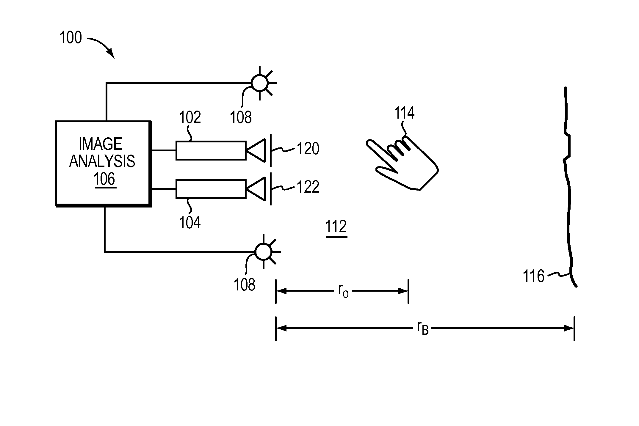
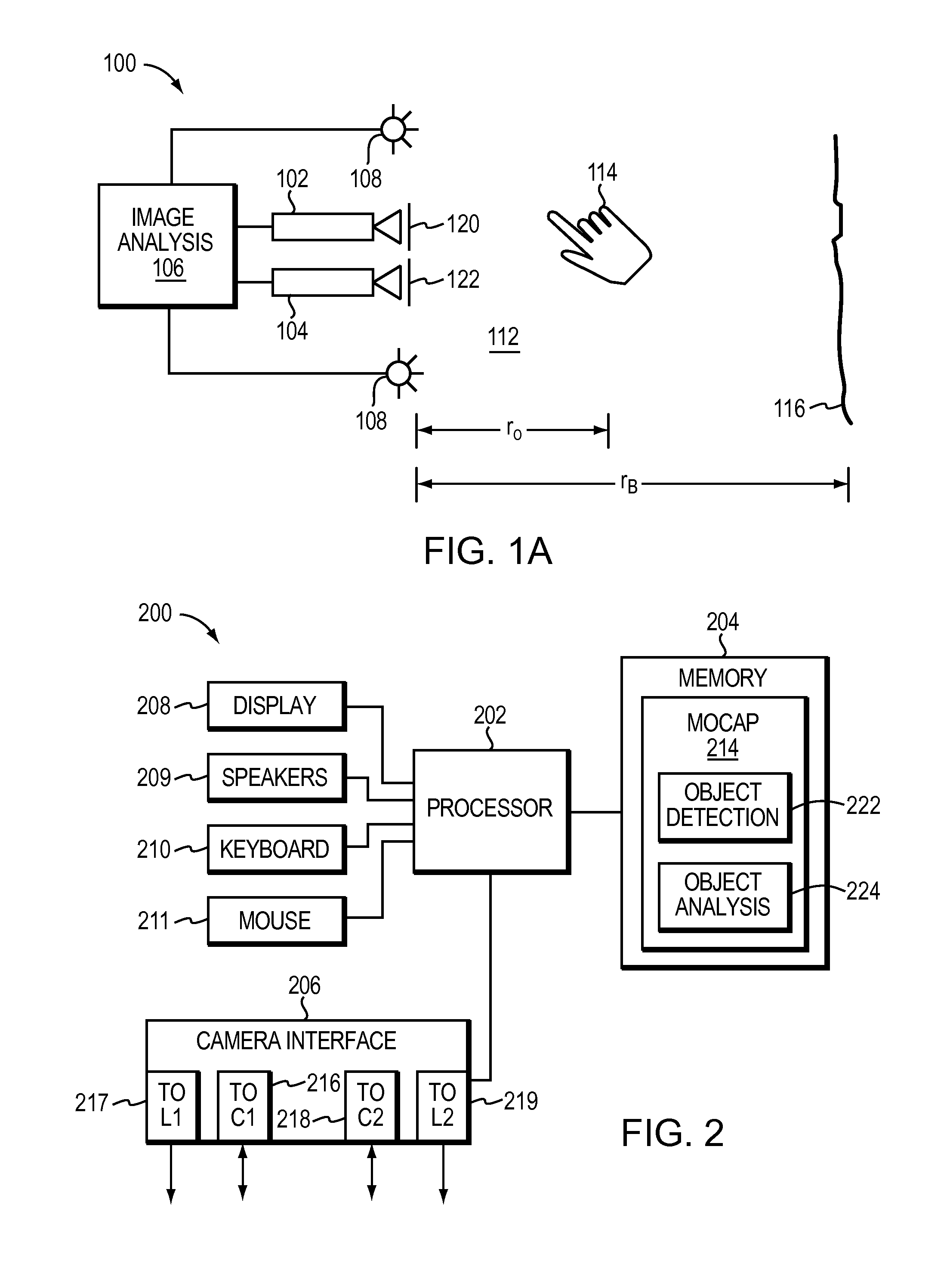
[0032]Refer first to FIG. 1A, which illustrates a system 100 for capturing image data that does not implement the present invention. System 100 includes a pair of cameras 102, 104 coupled to an image-analysis system 106. Cameras 102, 104 can be any type of camera, including cameras sensitive across the visible spectrum or, more typically, with enhanced sensitivity to a confined wavelength band (e.g., the infrared (IR) or ultraviolet bands); more generally, the term “camera” herein refers to any device (or combination of devices) capable of capturing an image of an object and representing that image in the form of digital data. For example, line sensors or line cameras rather than conventional devices that capture a two-dimensional (2D) image can be employed. The term “light” is used generally to connote any electromagnetic radiation, which may or may not be within the visible spectrum, and may be broadband (e.g., white light) or narrowband (e.g., a single wavelength or narrow band o...


PUM


Abstract

Imaging systems and methods optimize illumination of objects for purposes of detection, recognition and/or tracking by tailoring the illumination to the position of the object within the detection space. For example, feedback from a tracking system may be used to control and aim the lighting elements so that the illumination can be reduced or increased depending on the need.

Description

CROSS-REFERENCE TO RELATED APPLICATION[0001]This application claims priority to, and the benefits of, U.S. Provisional Application Ser. No. 61 / 724,073, filed on Nov. 8, 2012, the entire disclosure of which is hereby incorporated by reference.BACKGROUND[0002]The present disclosure relates generally to imaging systems and in particular to three-dimensional (3D) object detection, tracking and characterization using optical imaging.[0003]Motion-capture systems are used in a variety of contexts to obtain information about the conformation and motion of various objects, including objects with articulating members, such as human hands or human bodies. Such systems generally include cameras to capture sequential images of an object in motion and computers to analyze the images to create a reconstruction of an object's volume, position and motion. For 3D motion capture, at least two cameras are typically used.[0004]Image-based motion-capture systems rely on the ability to distinguish an obje...

Claims


Application Information

Patent Timeline
IPC IPC(8): H04N5/225G06V10/141G06V10/28
CPCH04N5/2256G06F3/017G06F3/0304G06V40/107G06V10/141G06V10/28
Inventor HOLZ, DAVID
Owner ULTRAHAPTICS IP TWO LTD
Why Eureka
Try Eureka