
Light Source Device

a technology of light source and light source, which is applied in the direction of lighting device details, light sources, lighting and heating equipment, etc., can solve problems such as heat dissipation, and achieve the effect of high smoothness

Active Publication Date: 2014-05-08
DARWIN PRECISIONS CORP
View PDF9 Cites 42 Cited by
  • Summary
  • Abstract
  • Description
  • Claims
  • Application Information

AI Technical Summary

Benefits of technology

The present invention provides a light source device that emits smoother light and has good heat dissipation properties.

Problems solved by technology

However, the distribution of light produced by the above design will typically form ring shaped areas of strong light.
In addition, since the light-emitting diode chip 30 is completely covered within the cavity 11, there will be heat dissipation problems.

Method used


Image

  • Light Source Device
  • Light Source Device
  • Light Source Device

Examples


Embodiment Construction

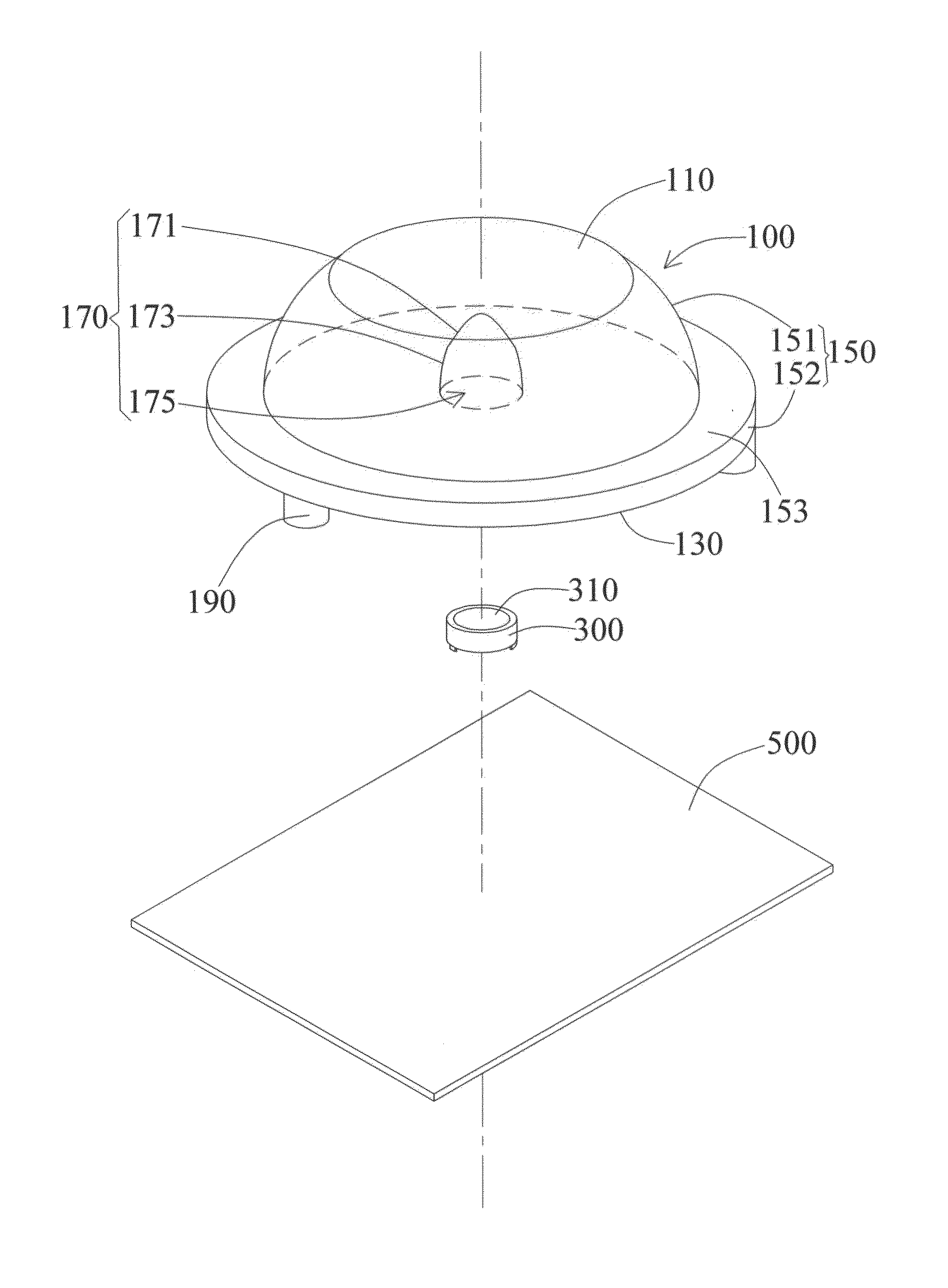
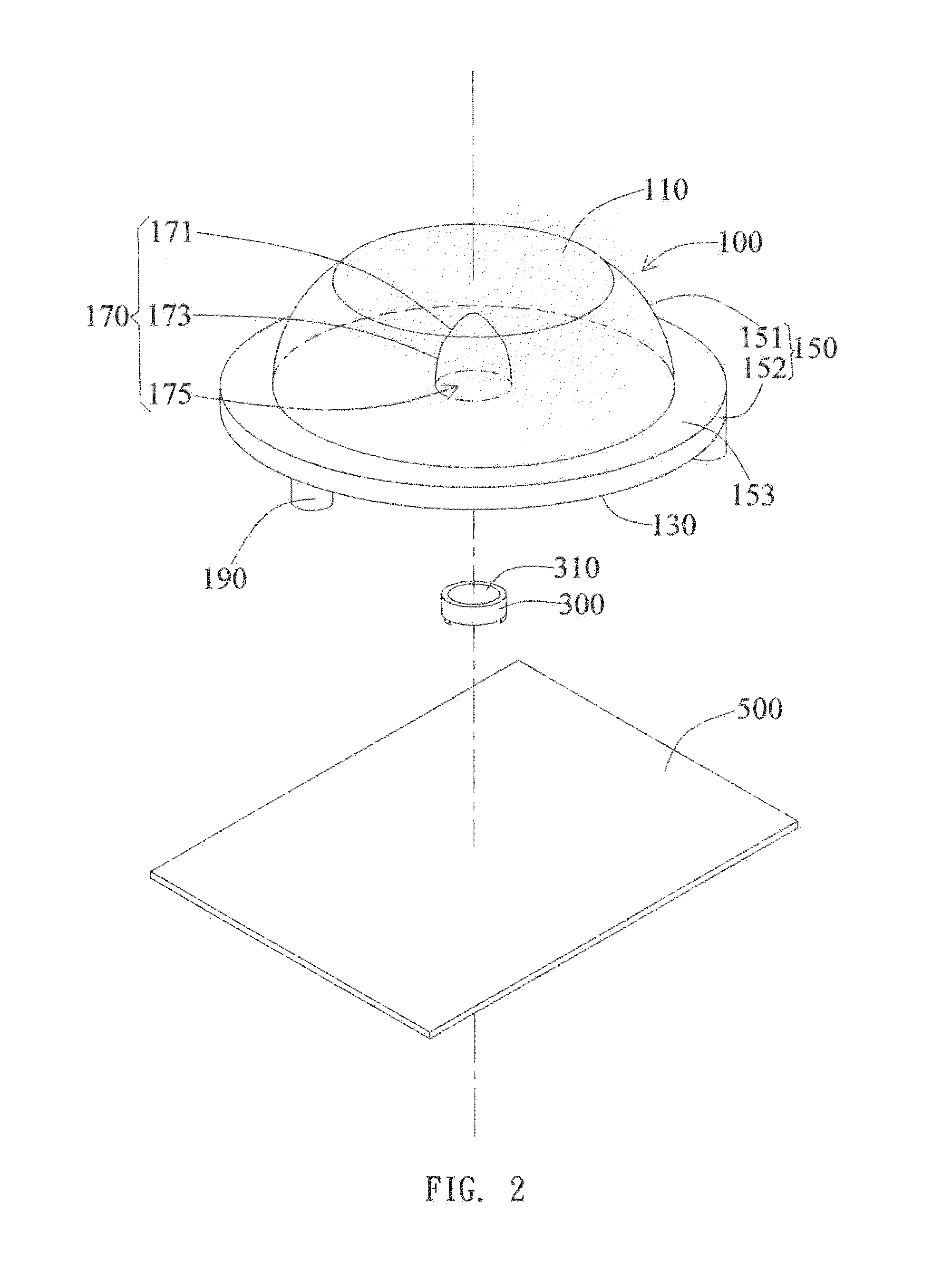
[0030]The present invention provides a light source device. In a preferred embodiment, the light source device is a light-emitting diode (LED) light source device. However, in other different embodiments, the light source device may also utilize other light sources that have an illumination area.

[0031]As shown in FIGS. 2 and 3A, the light source device includes a lens 100 and a light source 300. The lens 100 has a light-emitting top surface 110, a bottom surface 130 opposite to the light-emitting top surface 110, and an outer wall surface 150 extending and connecting from the bottom surface 130 to the light-emitting top surface 110. The lens 100 preferably is formed of a transparent material, such as transparent plastic or glass. For instance, the lens 100 may be formed of polycarbonate (PC), Polymethyl Methacrylate (PMMA), or the like. However, in other different embodiments, the lens 100 may also be formed from materials with light transmittance properties, wherein there may be an...


PUM


Abstract

A light source device includes a lens and a light source disposed under the lens. The lens has a light-emitting top surface and a bottom surface opposite to the light-emitting top surface. The bottom surface concaves towards the light-emitting top surface to form a hole and has a gouge surrounding the hole with an inclination towards the edge of the hole. The hole is formed from the surrounding of a first inner wall surface and a second inner wall surface. The light source is disposed below the bottom surface and corresponds to the hole.

Description

BACKGROUND OF THE INVENTION[0001]1. Field of the Invention[0002]The present invention generally relates to a light source device; particularly, the present invention relates to a light source device that has an external lens.[0003]2. Description of the Related Art[0004]Within various technical fields, especially to the field of display technology and illumination equipments, the design of light sources has always been an important aspect of light sources. Conventional light sources typically utilize light bulbs or incandescent tubes as light sources. As the technology of light-emitting diodes (LED) has matured and since LEDs have advantages of being small and being environmentally friendly by saving energy, LEDs have gradually become a mainstay on the market.[0005]In order to increase the illumination area in practical usage, the conventional light source as shown in FIG. 1 has a lens 10 disposed and covering on top of a light-emitting diode chip 30. As shown in FIG. 1, an empty cav...

Claims


Application Information

Patent Timeline
Patent Type & Authority Applications(United States)
IPC IPC(8): F21V5/04
CPCF21V5/04F21Y2115/10
Inventor WANG, CHUN-LINSHEN, YU-SHANCHANG, CHUNG-HSING
Owner DARWIN PRECISIONS CORP
Features
  • Generate Ideas
  • Intellectual Property
  • Life Sciences
  • Materials
  • Tech Scout
  • Unparalleled Data Quality
  • Higher Quality Content
  • 60% Fewer Hallucinations
Learn More