Device connector

a technology of device connectors and connectors, applied in the direction of coupling device connections, substation/switching arrangement details, electrical apparatus, etc., can solve the problems of operator erroneously accessing the fixing bolt, tool cannot be fit to the fixing bolt, and impact wrenches cannot be fit to the bolt head from behind

Active Publication Date: 2014-05-08
SUMITOMO WIRING SYST LTD
View PDF2 Cites 12 Cited by
  • Summary
  • Abstract
  • Description
  • Claims
  • Application Information

AI Technical Summary

Benefits of technology

[0007]The invention is directed to a device connector to be mounted and fixed to a case of a device. The device connector includes a case-side connector to be fixed to the case by fitting a tool to a bolt head on a fixing bolt and tightening the fixing bolt into the case. A mating connector is to be connected to the case-side connector and fixed to the case by tightening a connecting bolt into the case with the mating connector mounted on the case-side connector. An access prohibiting portion is provided on the mating connector and is configured to prohibit the tool from being fit to the bolt head by being arranged near the bolt head when the mating connector is mounted on the case-side connector. Thus, the tool cannot be fit to the fixing bolt and an operator cannot erroneously access the fixing bolt. Accordingly, the fixing bolt will not be broken by tightening when connecting the mating connector and rattling of the device connector will not be caused by erroneously loosening the fixing bolt when separating the connectors.
[0011]Enhanced strength could be achieved by thickening the projecting piece when forming the access prohibiting portion together with the shield shell by die cast molding.
[0012]However, air bubbles may be produced in the thick projection and cracks may be formed in the projection. However, the reinforcing rib enhances the strength of the access prohibiting portion without increasing the thickness of the projection.
[0013]The access prohibiting portion may have a size as to conceal the rear surface of the bolt head from behind in a tightening direction. Accordingly, the bolt head can be made invisible from behind in the tightening direction in a state where the mating connector is mounted on the case-side connector, thereby further preventing the operator from accessing the fixing bolt.

Problems solved by technology

Thus, the tool cannot be fit to the fixing bolt and an operator cannot erroneously access the fixing bolt.
Accordingly, the tool, such as an impact wrench, cannot be fit to the bolt head from behind.
The metal access prohibiting portion is stronger than one formed from resin and will be difficult to break even if contacted by the tool or another member.

Method used


Image

  • Device connector
  • Device connector
  • Device connector

Examples


first embodiment

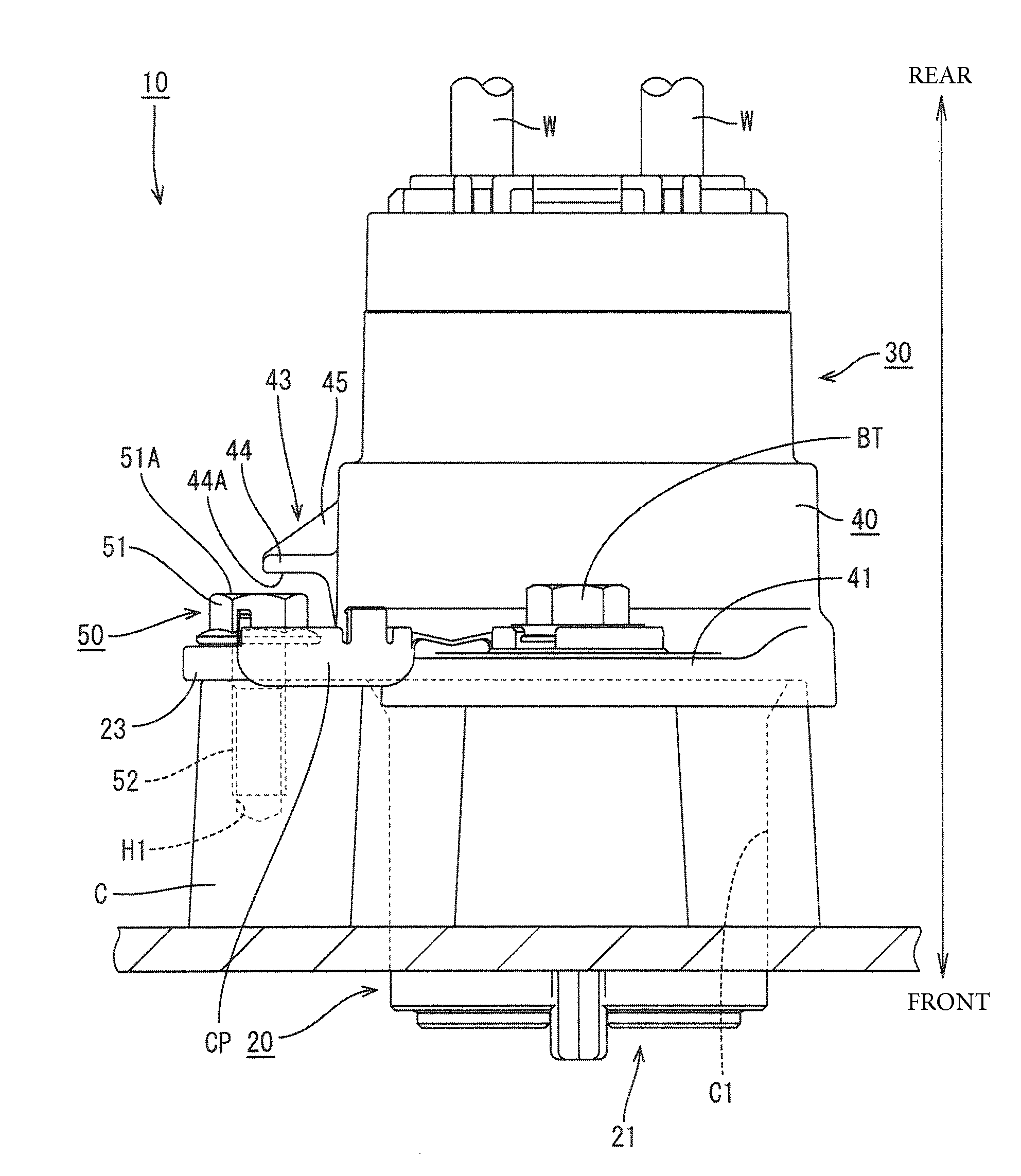
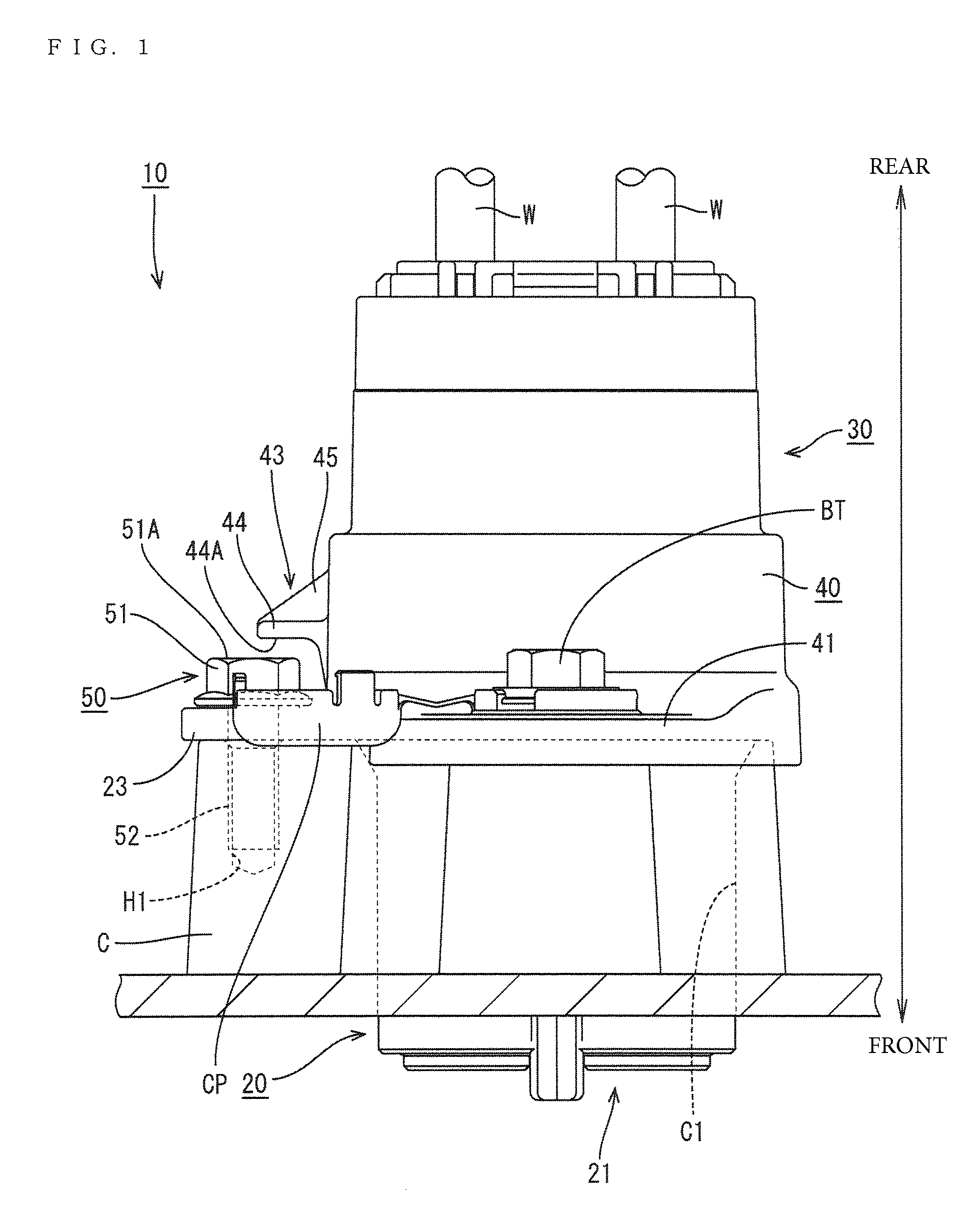
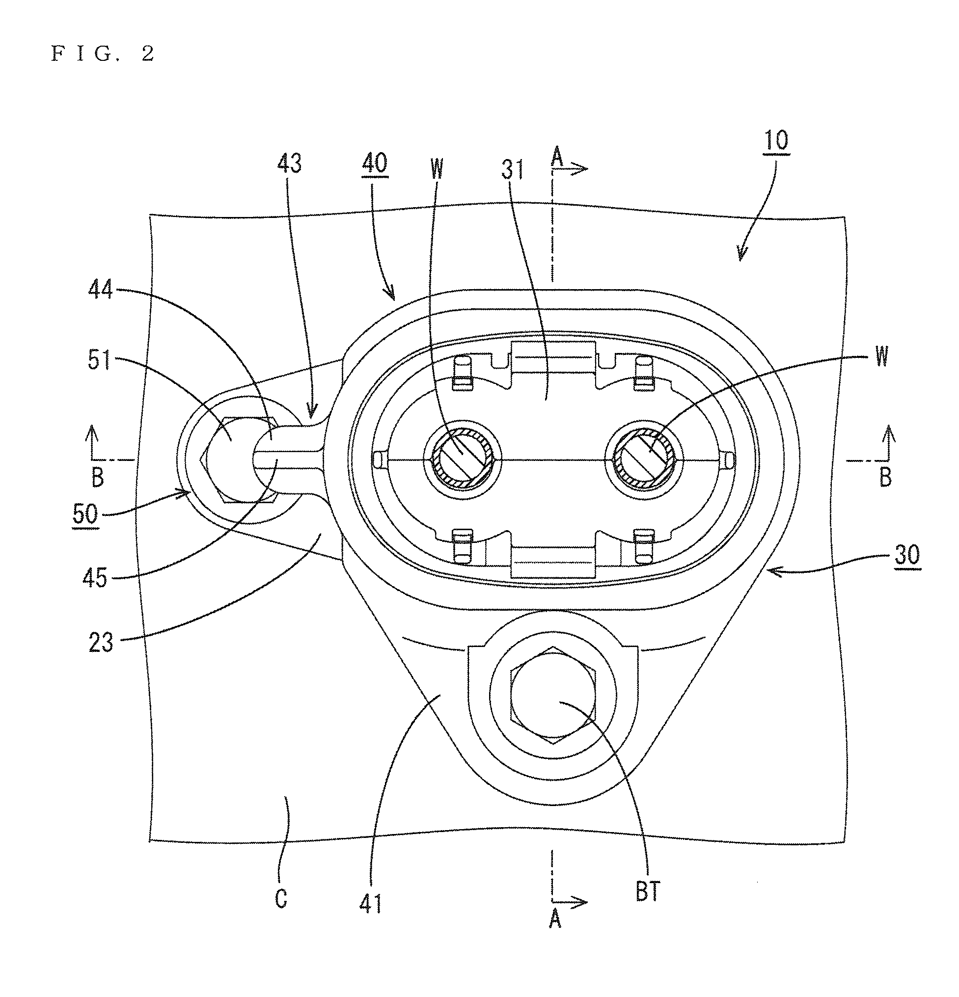
[0025]A device connector in accordance with the invention is identified by the numeral 10 in FIGS. 1 to 6. As shown in FIGS. 1 and 4, the device connector 10 includes a case-side connector 20 and a wire-side connector 30. The case-side connector 20 is to be fixed and fit into a mounting hole C1 in a case C. The wire-side connector 30 is provided on ends of wires W and is connected to the case-side connector 20. In the following description, forward and backward directions are based on a mounting direction of the device connector 10 onto the case C in FIG. 4, and a side to be mounted on the case C is referred to as a front side.

[0026]The case C of the device is made of electrical conductive metal and the mounting hole C1 enables the inside and outside of the case C to communicate. A fixing bolt hole H1 and a connecting bolt hole H2 are formed on the case C near the mounting hole C1. A fixing bolt 50 can be tightened into the fixing bolt hole H1 for fixing the case-side connector 20 t...

third embodiment

[0050]The device connector 12 of the third embodiment has a shield shell 240 with an access prohibiting portion 243 in the form of a box that is open forward, as shown in FIGS. 9 and 10. The access prohibiting portion 143 completely covers the entire bolt head 51 of the fixing bolt 50 when a wire-side connector 30 and a case-side connector 20 are connected properly. Specifically, the bolt head 51 of the fixing bolt 50 is invisible from behind and from a lateral side as shown in FIG. 9 when the wire-side connector 30 is mounted on the case-side connector 20, thereby further preventing erroneous access to the fixing bolt 50.

[0051]The invention is not limited to the above described embodiments. For example, the following embodiments also are included in the scope of the invention.

[0052]The access prohibiting portion 43, 143 is arranged behind and in proximity to the bolt head 51 of the fixing bolt 50 in the first and second embodiments and the bolt head 51 is covered completely in the ...


PUM


Abstract

A device connector to be mounted and fixed to a case of a device includes a case-side connector to be fixed to the case by fitting a tool such as an impact wrench to a bolt head provided on a fixing bolt and tightening the fixing bolt into the case, a mating connector to be connected to the case-side connector and fixed to the case by tightening a connecting bolt into the case with the mating connector mounted on the case-side connector, and an access prohibiting portion provided on the mating connector and configured to prohibit the tool from being fitted to the bolt head by being arranged in proximity to the bolt head of the fixing bolt when the mating connector is mounted on the case-side connector.

Description

BACKGROUND[0001]1. Field of the Invention[0002]The invention relates to a device connector.[0003]2. Description of the Related Art[0004]U.S. Pat. No. 8,011,977 discloses a device connector to be fixed to a case of a device. This device connector has a case-side housing to be fixed to the case of the device while being covered by a case-side shell made of metal, and a mating housing to be connected to the case-side housing while being covered by a mating shell made of metal. A bolt is used to fix the case-side shell and the case-side housing to the case. The mating housing then is fit lightly to the case-side housing. A connecting bolt on the mating shell then is tightened into the case-side shell to connect the mating housing and the case-side housing and also to fix the mating shell and the case-side shell in an electrically connected state.[0005]The fixing bolt and the connecting bolt of the above described connector may be identical or similar. Thus, an operator may break the fix...

Claims


Application Information

Patent Timeline
Patent Type & Authority Applications(United States)
IPC IPC(8): H01R13/621
CPCH01R13/621H01R13/748H01R13/447H01R13/60H01R13/6397
Inventor ISHIBASHI, TAKESHIOKAYASU, YASUSHI
Owner SUMITOMO WIRING SYST LTD
Why Eureka
Try Eureka