Pitot tube velocimeter system

Active Publication Date: 2014-05-15
ADAMS PHILLIP M
View PDF14 Cites 18 Cited by
  • Summary
  • Abstract
  • Description
  • Claims
  • Application Information

AI Technical Summary

Benefits of technology

The patent describes an apparatus for sensing position based on flow velocity. It uses at least two pitot tubes to measure the effects of motion in three degrees of freedom. The system can have more pitot tubes to measure in more degrees of freedom, but an apparatus with only three degrees of freedom can provide useful information. The technical effect is that the apparatus provides accurate position sensing even in flowing systems with limited motion degrees of freedom.

Problems solved by technology

However, there are situations where GPS is not operable.
For example, GPS jammers can render GPS receivers useless.
Likewise, within buildings, particularly fortified structures, signals may not be receivable.
Within caves and underwater, GPS signals likewise cannot be received.
However, the accelerometers themselves may be sophisticated micro-electromechanical structures and can be expensive.
The control circuits needed to interface with the accelerometers may also be subject to natural and man-made interference phenomena.

Method used


Image

  • Pitot tube velocimeter system
  • Pitot tube velocimeter system
  • Pitot tube velocimeter system

Examples


Embodiment Construction

[0029]It will be readily understood that the components of the present invention, as generally described and illustrated in the drawings herein, could be arranged and designed in a wide variety of different configurations. Thus, the following more detailed description of the embodiments of the system and method of the present invention, as represented in the drawings, is not intended to limit the scope of the invention, as claimed, but is merely representative of various embodiments of the invention. The illustrated embodiments of the invention will be best understood by reference to the drawings, wherein like parts are designated by like numerals throughout.

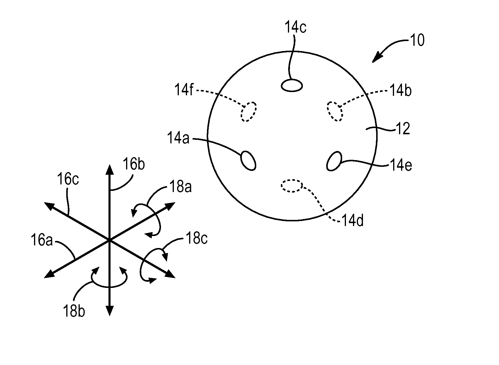
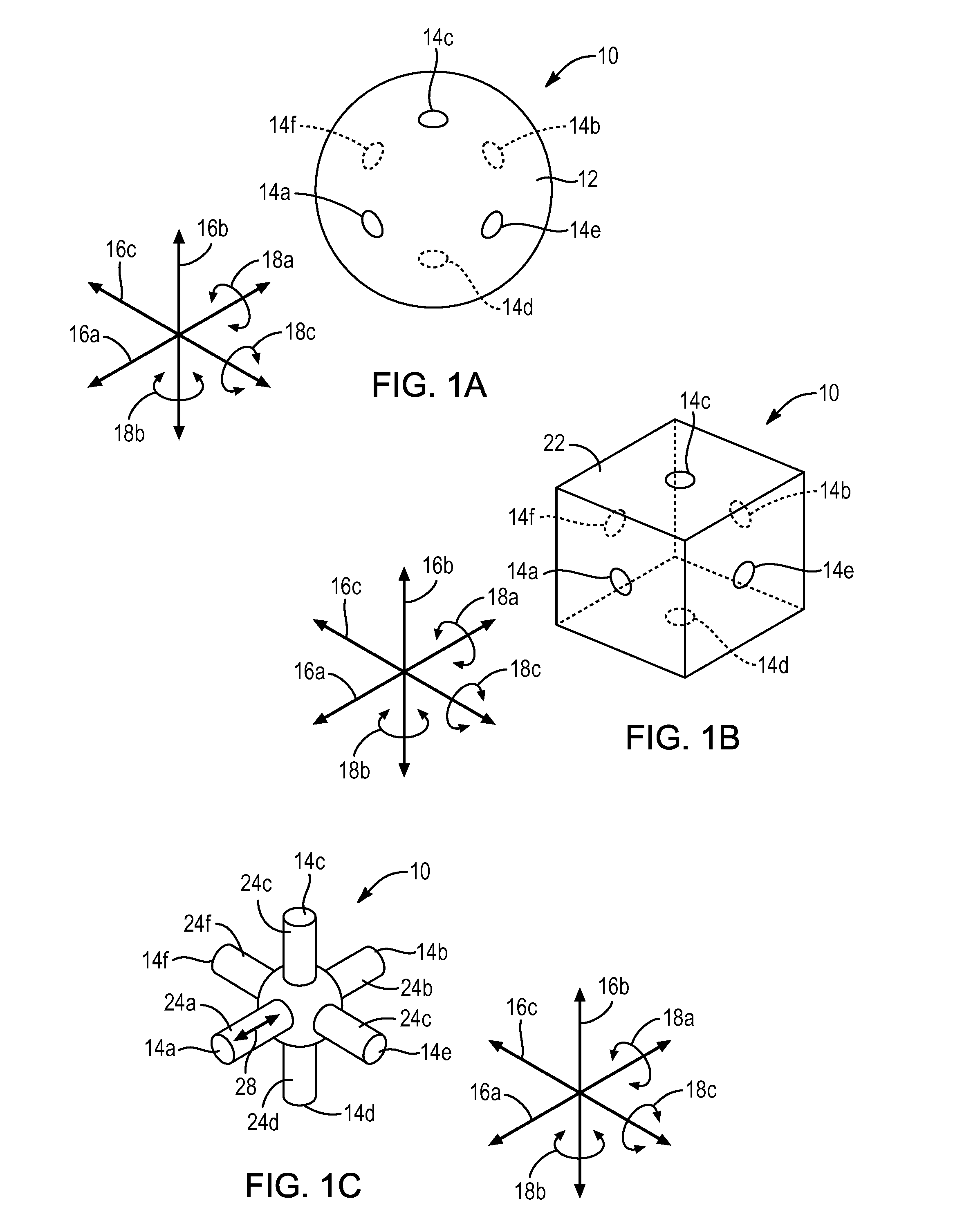
[0030]FIG. 1A illustrates a sensor system 10 for measuring distance according to fluid flow velocity. The sensor system 10 may include a spherical surface 12 that is substantially hollow or substantially occupied (filled) with material. The spherical surface 12 defines apertures 14a-14f.

[0031]In the illustrated embodiment there...


PUM


Abstract

An apparatus and method for sensing position according to flow velocity includes at least two pitot tubes each defining a central axis is along mutually orthogonal axes. Each of at least two pressure sensors is positioned in fluid communication with a corresponding one of the at least two pitot tubes. A controller receives outputs from the at least two pressure sensors and analyzes to determine at least one of an angular and translational velocity according to the outputs. A distance traveled is then determined according to the at least one of an angular and translational velocity. Corresponding methods of use and calibration are also disclosed.

Description

BACKGROUND[0001]1. The Field of the Invention[0002]This invention relates to navigation systems, and, more particularly, to relative-position navigation systems measuring distance and direction according to movement of a sensor.[0003]2. The Background Art[0004]The Global Positioning System (GPS) is the most common navigation system in use today. As known in the art, GPS relies on receiving signals from orbiting satellites to determine the position of a GPS receiver. This system has been very reliable and accurate and has therefore found many civilian and military applications.[0005]However, there are situations where GPS is not operable. For example, GPS jammers can render GPS receivers useless. Likewise, within buildings, particularly fortified structures, signals may not be receivable. Within caves and underwater, GPS signals likewise cannot be received.[0006]An alternative method, for position sensing is to use accelerometers as the basis for a Relative Positioning System (RPS). ...

Claims


Application Information

Patent Timeline
IPC IPC(8): G01B5/14G01F1/46
CPCG01F1/46G01B5/14G06F3/0346G01P5/16G01P21/025G01C25/00G01P5/165G01P21/00
Inventor ADAMS, PHILLIP M.
Owner ADAMS PHILLIP M
Why Eureka
Try Eureka