Multiple strand dental flosser
a multi-strand, dental flosser technology, applied in the field of disposable dental flossers, can solve the problems of low friction coefficient, stretching, shredding and breaking in vigorous use, and achieve the effect of reducing the friction coefficient of the lead strand, facilitating the use of users, and increasing strength
- Summary
- Abstract
- Description
- Claims
- Application Information
AI Technical Summary
Benefits of technology
Problems solved by technology
Method used
Image
Examples
second embodiment
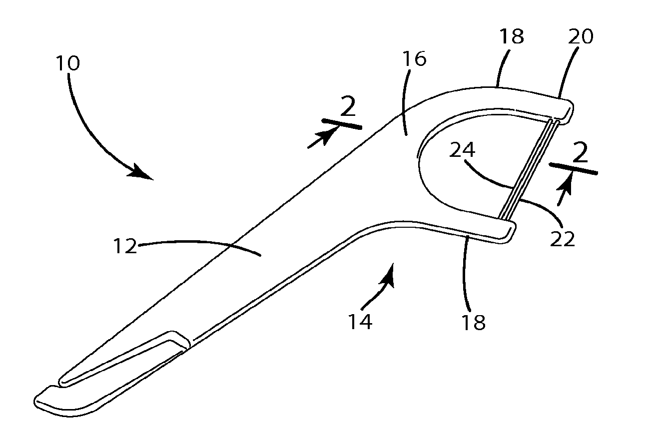
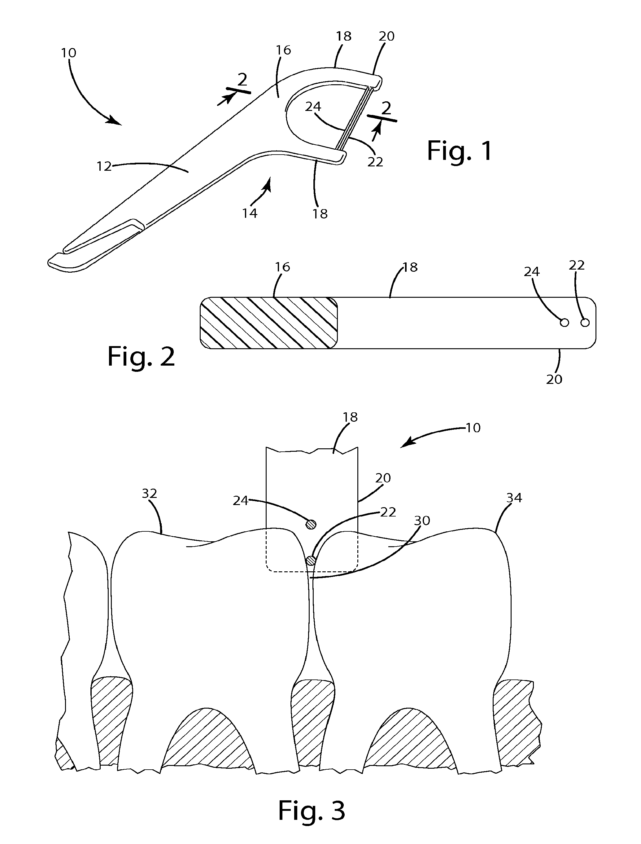
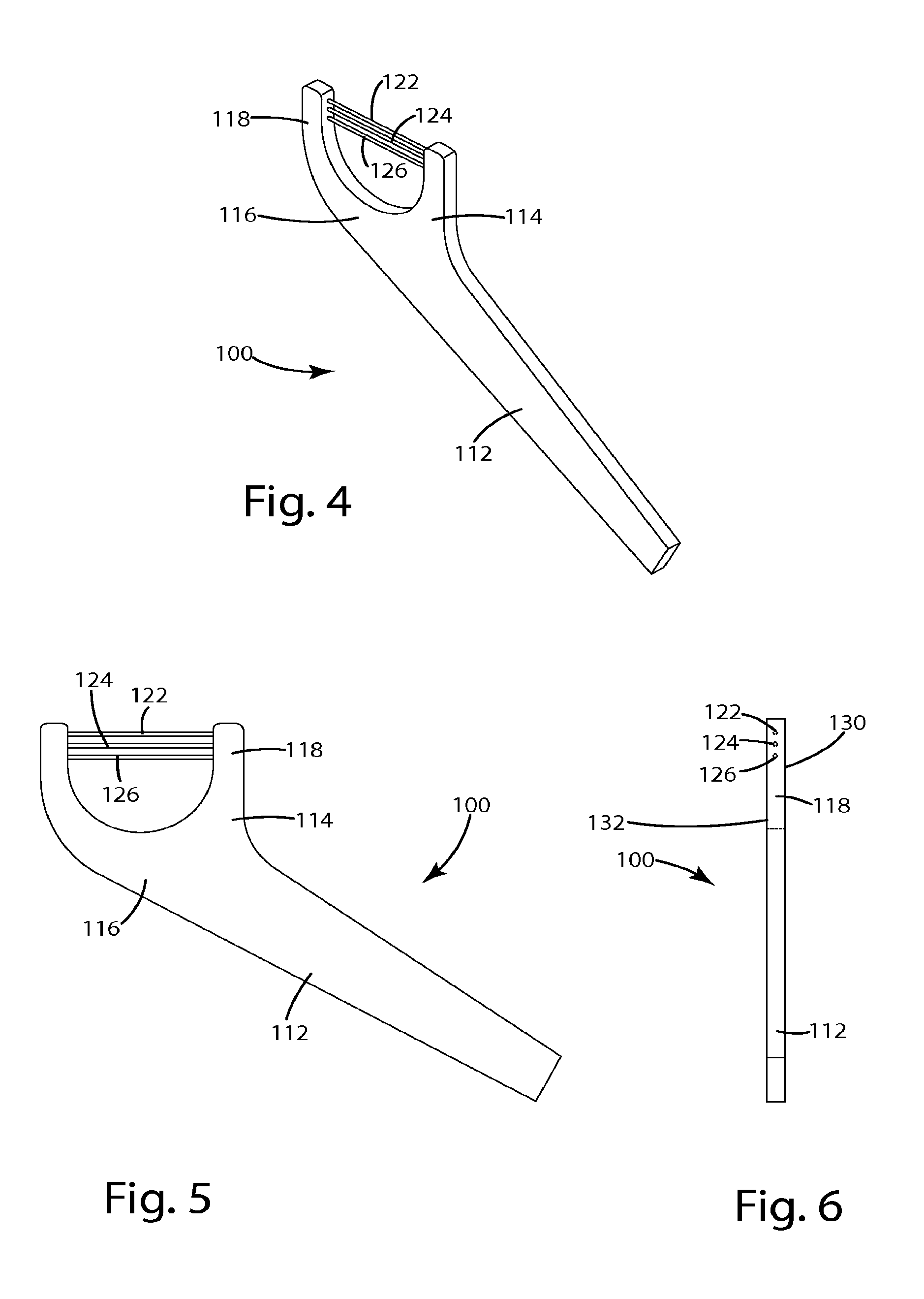
[0053]the dental flosser is shown in FIGS. 4-6. In this embodiment, the dental flosser 100 includes a handle part 112 and a head part 114 that are substantially similar to the dental flosser 10 described above. The head part 114 includes a base 116 and a pair of arms 118 extending from the base 116. Three strands of floss 122, 124, 126 extend between the arms 118. In the illustrated embodiment, the three strands 122, 124 and 126 are generally parallel to each other, and are spaced about five millimeters from each other, although the spacing may be varied. FIG. 6 (a side view of the flosser 100) shows the ends of the floss strands 122, 124, 126, in an embodiment wherein in the floss strands extend through the arms 118. As shown, the floss strands 122, 124, 126 are aligned when viewed down the length of the arms 118, and are positioned generally along the midline of the width of the flosser arms 118 between a front surface 130 and a rear surface 132 of the flosser arms 118. At least o...
fourth embodiment
[0055]the dental flosser is shown in FIGS. 10-13. In this embodiment, the flosser 300 includes a handle part 312 and a head 314 having a base 316 and a pair of arms 318 extending from the base 316. The flosser 300 and flosser arms 318 generally include a front surface 330, a rear surface 332, and a width defined between the front and rear surfaces 330, 332. As shown, each arm includes a distal end portion 320 that projects outwardly from the front 330 and rear 332 surfaces of the arm 318, such that the distal end portion has a width that is greater than the width of the arms 318. A pair of dental floss strands 322, 324 extend between the arms 318 at the distal end portion 320 of the arms 318. In contrast to the previously described embodiments, the strands 322, 324 of this embodiment are aligned in a plane that extends generally perpendicular to the planes defined by the front 330 and rear 332 surfaces of the flosser 300, and perpendicular to the longitudinal extent of the arms 318....
fifth embodiment
[0056]the flosser is shown in FIGS. 14-17. In this embodiment, the flosser 400 includes a handle 412, head 414, base 416 and arms 418 that are substantially the same as the first described embodiment. The arms 418 each include a longitudinal length extending between the distal end 420 of the arm 418 and the base 416, and a width extending between the front surface 430 of the arm 418 and the rear surface 432 of the flosser arm 418. A pair of dental floss strands 422, 424 extend between the arms 418. The strands 422, 424 extend generally parallel to each other, and are spaced apart along both the longitudinal length of the arms and the width of the arms, such that the strands 422, 424 are staggered along the length of the arms 418. As shown in FIGS. 14-17 (which illustrate how the floss strands 422, 424 may extend completely through the arms 418), the floss strands 422, 424 are positioned such that the lead strand 422 is nearer to the front surface 430 and the follower strand 424 is n...
PUM
 Abstract
Description
Claims
Application Information
 - R&D
- Intellectual Property
- Life Sciences
- Materials
- Tech Scout
- Unparalleled Data Quality
- Higher Quality Content
- 60% Fewer Hallucinations
Browse by: Latest US Patents, China's latest patents, Technical Efficacy Thesaurus, Application Domain, Technology Topic, Popular Technical Reports.
© 2025 PatSnap. All rights reserved.Legal|Privacy policy|Modern Slavery Act Transparency Statement|Sitemap|About US| Contact US: help@patsnap.com


