Clamp fixture and related clamp apparatus

a clamping device and clamping technology, applied in the field of clamping devices, can solve the problems of inconvenient operation, low operational efficiency, easy loosening of work pieces, etc., and achieve the effect of quick and stably fixing and loosening work pieces, effective constraining the rotation of actuating components, and convenient structur

Inactive Publication Date: 2014-05-15
WISTRON CORP
View PDF1 Cites 4 Cited by
  • Summary
  • Abstract
  • Description
  • Claims
  • Application Information

AI Technical Summary

Benefits of technology

[0005]The present invention provides a clamp fixture with advantages of easy operation and preferable fixing efficiency and a related clamp apparatus for solving above drawbacks.
[0014]The present invention can rapidly and stably fix and loose the work piece. The clamp fixture of the present invention utilizes the linkage to drive the contacting component to tightly press the work piece. The actuating component of the present invention can be constrained by a combination of the pushing component and the bridging component, the actuating component can not rotate relative to the base when the pushing component rotates relative to the bridging component at the predetermined angle (such as the straight arrangement of the first shaft, the third shaft and the fourth shaft), so that the contacting component can tightly press over the work piece. The reacting force from the work piece may generate a rotary moment at the first end of the actuating component, the combination of the pushing component and the bridging component can balance off the rotary moment, to effectively constrain the rotation of the actuating component relative to the base. Comparing to the prior art, the clamp fixture and the related clamp apparatus of the present invention has advantages of easy structure, simple operation and low manufacturing cost. The present invention can stably fix the work piece to advance the producing efficiency and the manufacturing accuracy, so as to increase the market competition of the product.

Problems solved by technology

The convention screw fixture has drawbacks of inconvenient operation and low operational efficiency, for example, a specific tool is applied to execute the locking and unlocking motion.
However, the work piece is easily loosened when vibration of the work piece is violent or resilient fatigue of the resilient unit is generated, so the conventional resilient clamp fixture can not tightly fix the work piece.
The conventional fixture can not stably fix the work piece, which decreases manufacturing accuracy of the processing procedure.

Method used


Image

  • Clamp fixture and related clamp apparatus
  • Clamp fixture and related clamp apparatus
  • Clamp fixture and related clamp apparatus

Examples


Embodiment Construction

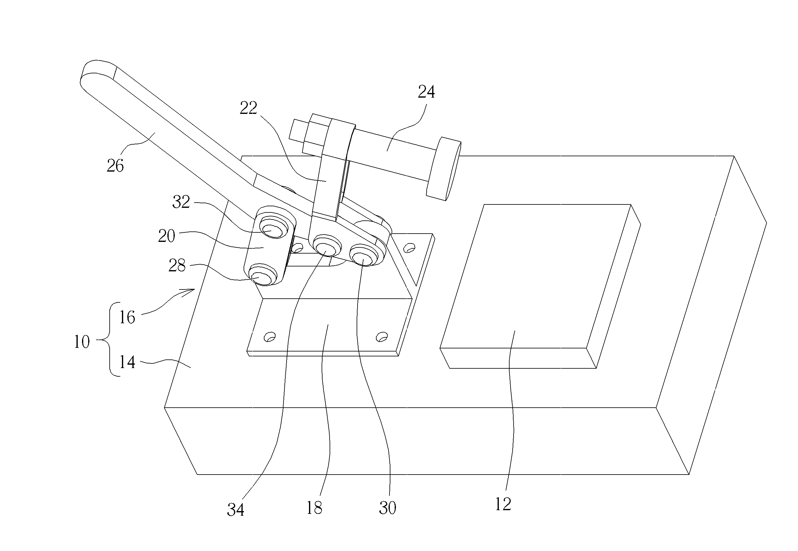
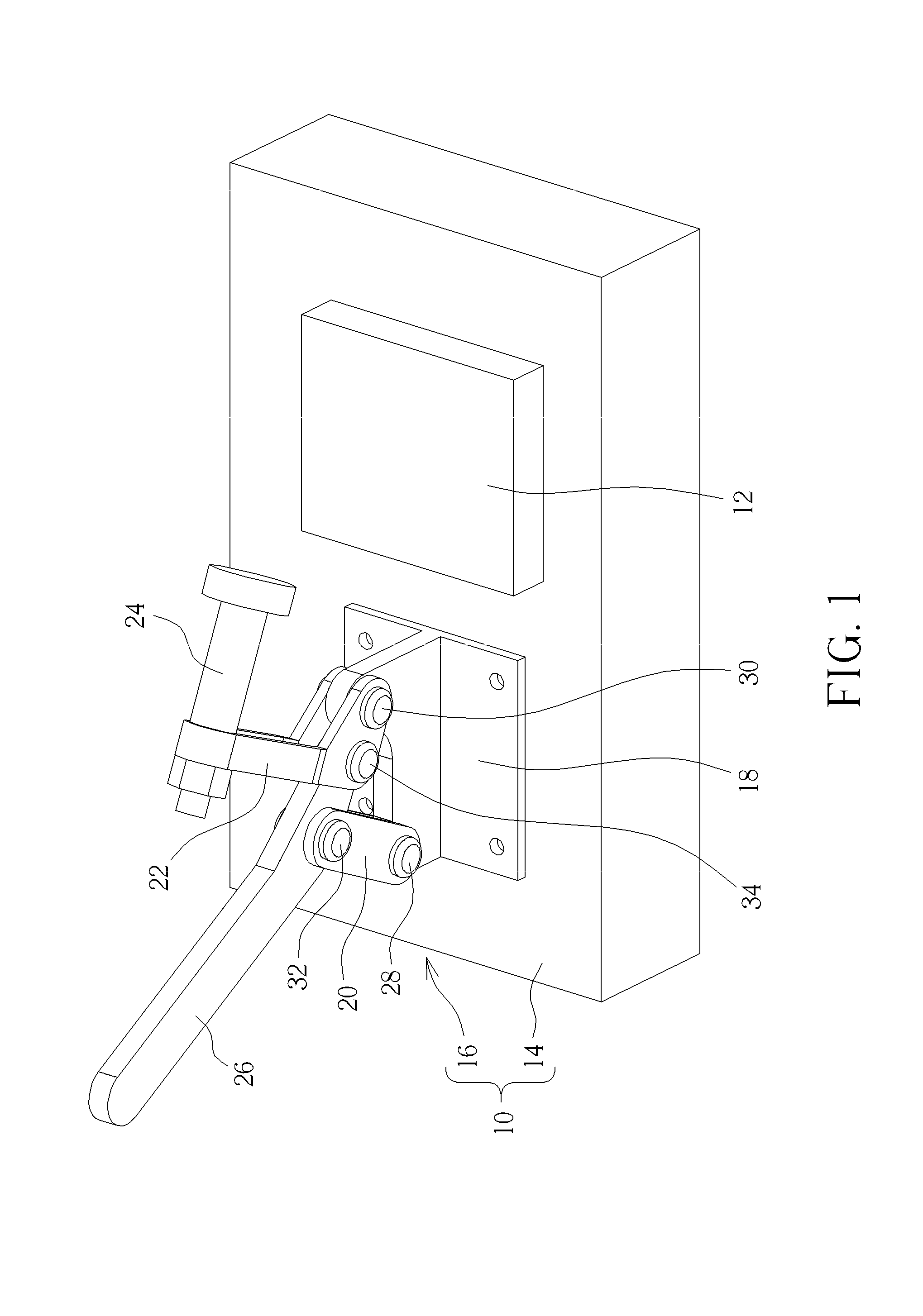
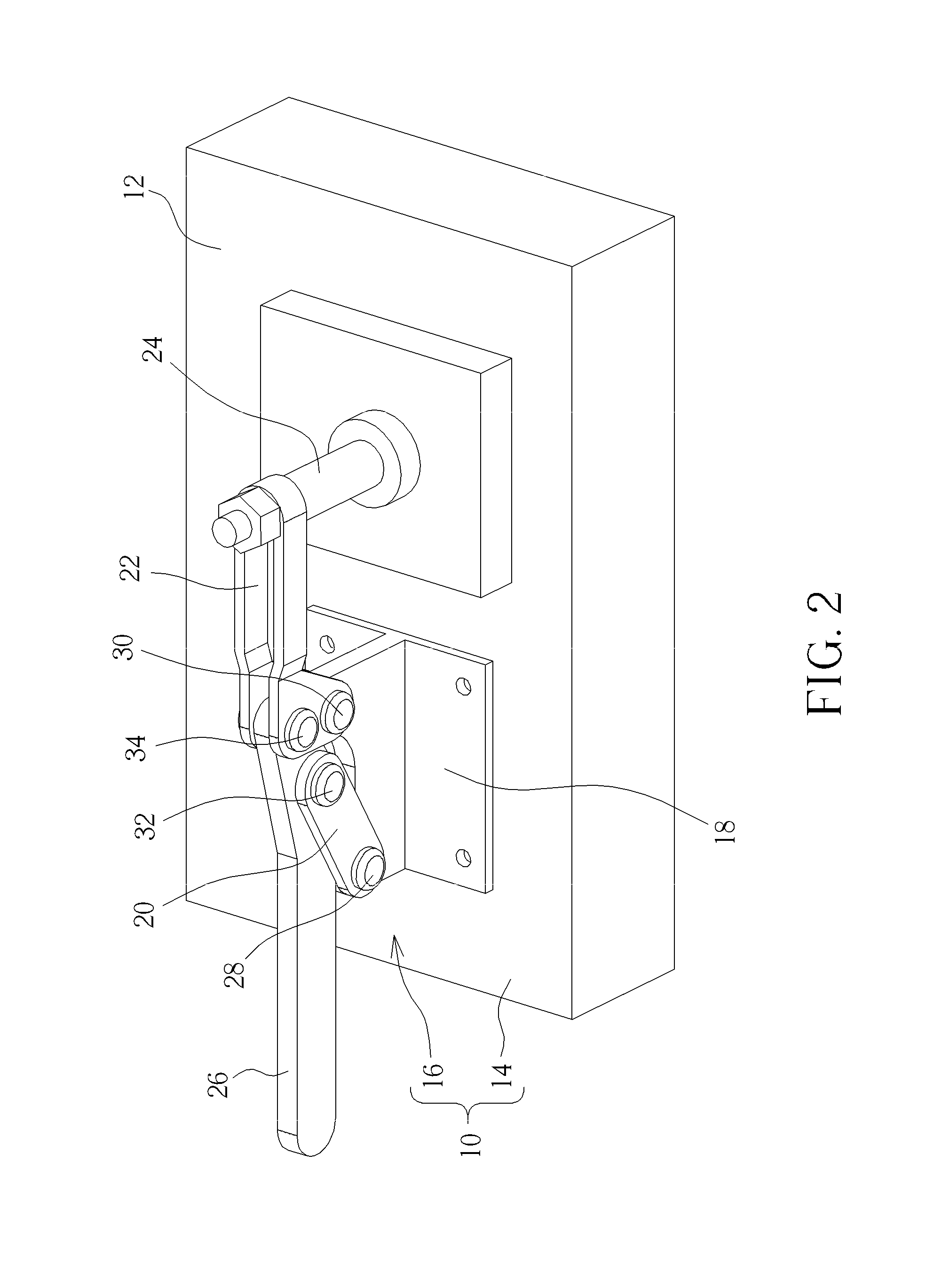
[0020]Please refer to FIG. 1 and FIG. 2. FIG. 1 and FIG. 2 respectively are diagrams of a clamp apparatus 10 in different operational modes according to an embodiment of the present invention. The clamp apparatus 10 can fix a work piece 12 to execute the processing procedure. The clamp apparatus 10 includes a foundation 14 and a clamp fixture 16. Please refer to FIG. 3. FIG. 3 is an exploded diagram of the clamp fixture 16 according to the embodiment of the present invention. The clamp fixture 16 is disposed on the foundation 14 to press the work piece 12 by linkage, so as to constrain a movement of the work piece 12 relative to the foundation 14.

[0021]As shown in FIG. 3, the clamp fixture 16 includes a base 18, a bridging component 20, an actuating component 22, a contacting component 24 and a pushing component 26. The base 18 is disposed on the foundation 14. The base 18 includes a first side 181 and a second side 183. The bridging component 20 includes a first end 201 and a secon...


PUM


Abstract

A clamp fixture includes a base, a bridging component, an actuating component, a contacting component and a pushing component. The base is disposed on a foundation. A first end of the bridging component pivots to a first side of the base. A first end of the actuating component pivots to a second side of the base. The contacting component is disposed on a second end of the actuating component. The pushing component includes a body, two pivot structures and a handle. The pivot structures are disposed on an end of the body for respectively pivoting to the bridging component and the actuating component. The handle is disposed on the other end of the body. The handle moves at a first direction, the bridging component and the actuating component can move at a second direction, so as to move the contacting component close to or away from a work piece.

Description

BACKGROUND OF THE INVENTION[0001]1. Field of the Invention[0002]The present invention relates to a clamp fixture and a related clamp apparatus, and more particularly, to a clamp fixture and a related clamp apparatus with advantages of easy operation and preferable fixing efficiency.[0003]2. Description of the Prior Art[0004]For fixing a work piece, a conventional fixture utilizes screws or resilient components to provide constraint function. The conventional screw fixture uses a tool, such as the screw driver. The tool presses the screw to rotate, so as to lock the screw into the thread hole. The convention screw fixture has drawbacks of inconvenient operation and low operational efficiency, for example, a specific tool is applied to execute the locking and unlocking motion. The conventional resilient clamp fixture includes the resilient components, such as the spring and the resilient unit. The resilient component utilizes the resilient recovering force to press the work piece. How...

Claims


Application Information

Patent Timeline
Patent Type & Authority Applications(United States)
IPC IPC(8): B25B5/12
CPCB25B5/12
Inventor CHENG, XIU-FENG
Owner WISTRON CORP
Why Eureka
Try Eureka