

Shrinkage compensated seal assembly and related methods
a sealing assembly and compression technology, applied in sealing/packing, mechanical equipment, borehole/well accessories, etc., to achieve the effect of reducing tolerances, high energizing sources, and increasing costs
- Summary
- Abstract
- Description
- Claims
- Application Information
AI Technical Summary
Benefits of technology
Problems solved by technology
Method used
Image

Examples
Embodiment Construction
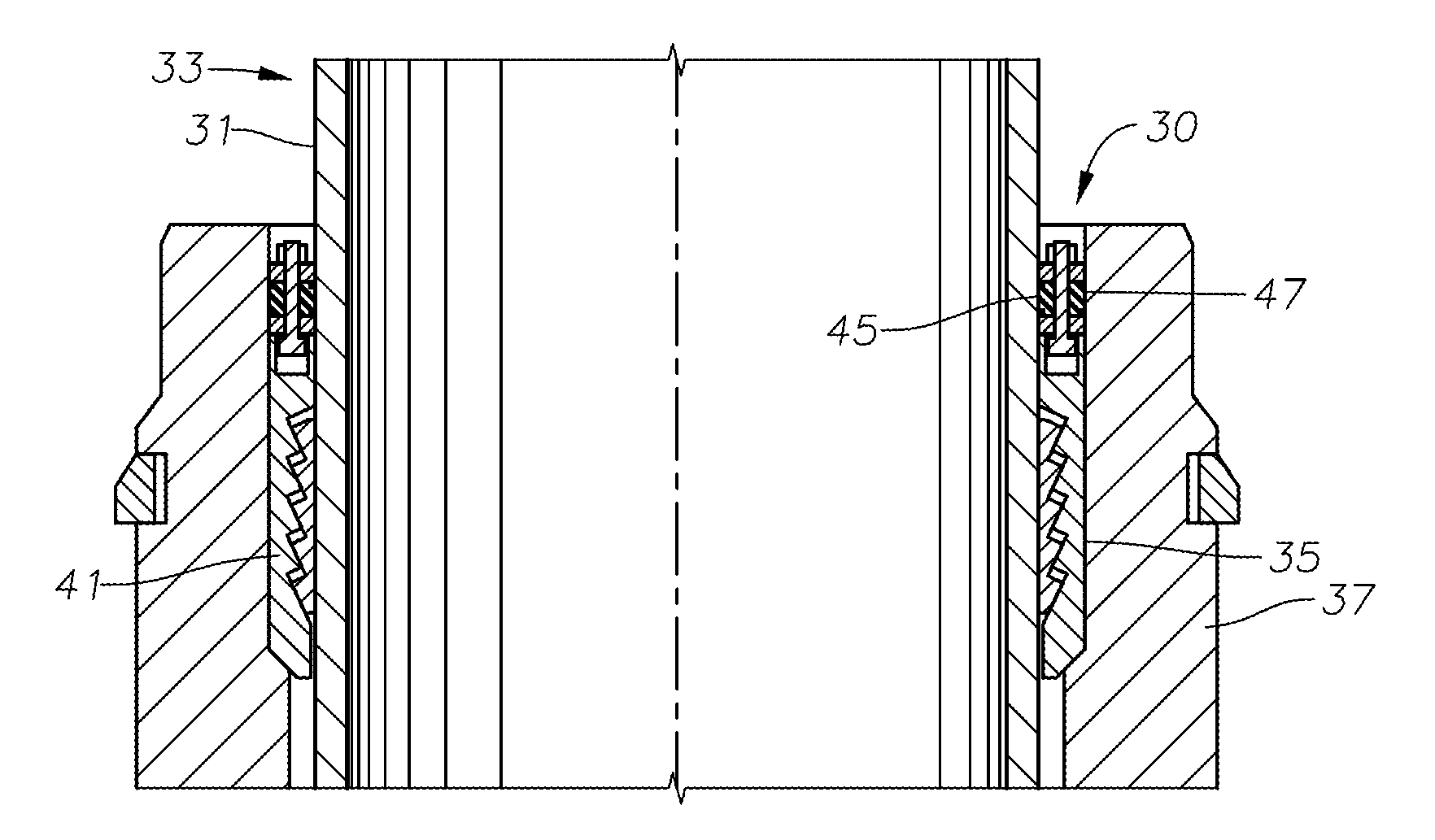
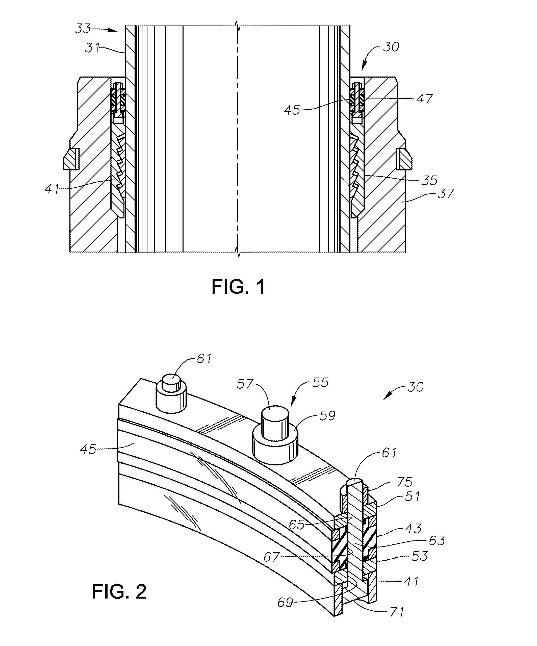
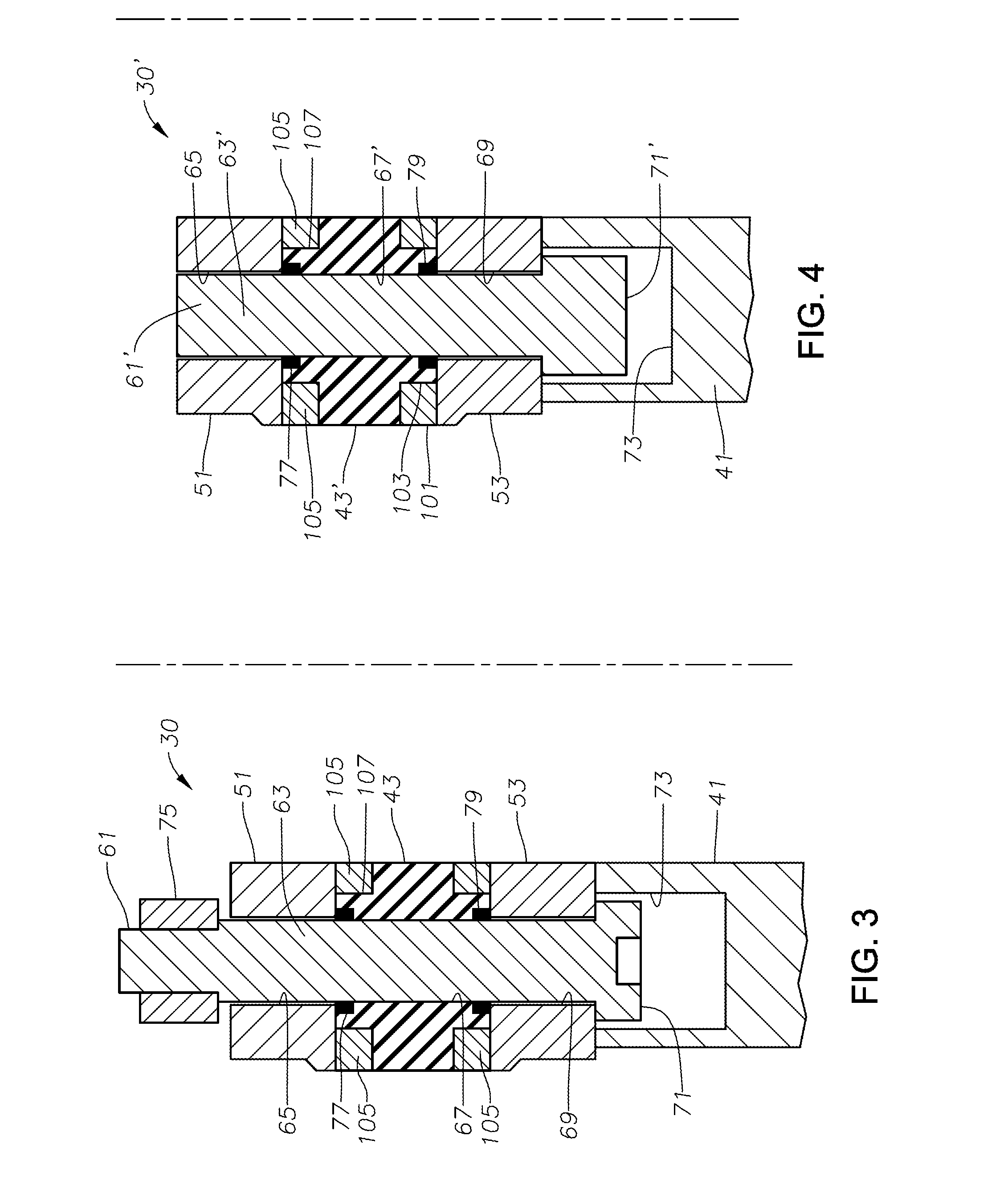
[0028]The present invention will now be described more fully hereinafter with reference to the accompanying drawings, which illustrate embodiments of the invention. This invention may, however, be embodied in many different forms and should not be construed as limited to the illustrated embodiments set forth herein. Rather, these embodiments are provided so that this disclosure will be thorough and complete, and will fully convey the scope of the invention to those skilled in the art. Like numbers refer to like elements throughout. Prime notation, if used, indicates similar elements in alternative embodiments.
[0029]As production of oil and gas occurs at greater water and surface depths the temperature variation becomes wider and more critical to the effectiveness of elastomer seals. Accordingly, a constant effectiveness of the seal 43, especially at higher pressures, has become more desirable. Various embodiments of the present invention provide compensation for the behavior of the ...
PUM
 Abstract
Description
Claims
Application Information