Eureka AIR delivers breakthrough ideas for toughest innovation challenges, trusted by R&D personnel around the world.

Four-wheel-drive vehicle

Active Publication Date: 2014-05-15
JTEKT CORP
View PDF7 Cites 16 Cited by
  • Summary
  • Abstract
  • Description
  • Claims
  • Application Information

AI Technical Summary

Benefits of technology

This invention is about a four-wheel-drive vehicle that has a special driving system for the wheels. The vehicle has a main driving force transmission system that sends power to the main wheels, and an additional driving force transmission system that sends power to the auxiliary wheels. The vehicle also has an operation-receiving device for starting the vehicle, and a control device that manages the additional driving force transmission system. The control device uses a special clutch to transmit power and a special device that can adjust the amount of power being transmitted. The control device also determines the type of road surface that the vehicle is driving on and adjusts the clutch accordingly to ensure the vehicle can still transmit power properly. The technical effect of this invention is to ensure that the vehicle can drive on different road surfaces and still have proper power transmission.

Problems solved by technology

In the four-wheel-drive vehicle described in JP 2012-61923 A, if the main drive wheels slip at the time when the vehicle starts in the two-wheel drive mode, it may not be possible to shift the vehicle into the four-wheel-drive mode because recessed portions and projected portions in the dog clutch cannot be engaged with each other.
In such a case, because the vehicle starts before the control device determines whether the coefficient of friction of the road surface is low, the dog clutch cannot be engaged before the vehicle starts.
Therefore, when the main drive wheels slip, it may not be possible to converge the slip of the main drive wheels by shifting the vehicle into the four-wheel drive mode.

Method used


Image

  • Four-wheel-drive vehicle
  • Four-wheel-drive vehicle
  • Four-wheel-drive vehicle

Examples


Embodiment Construction

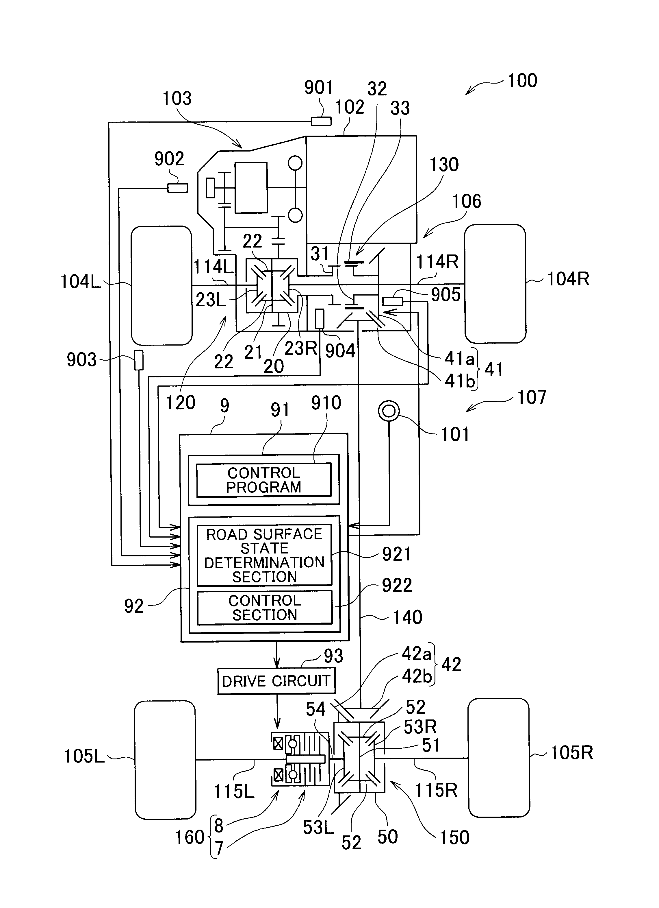
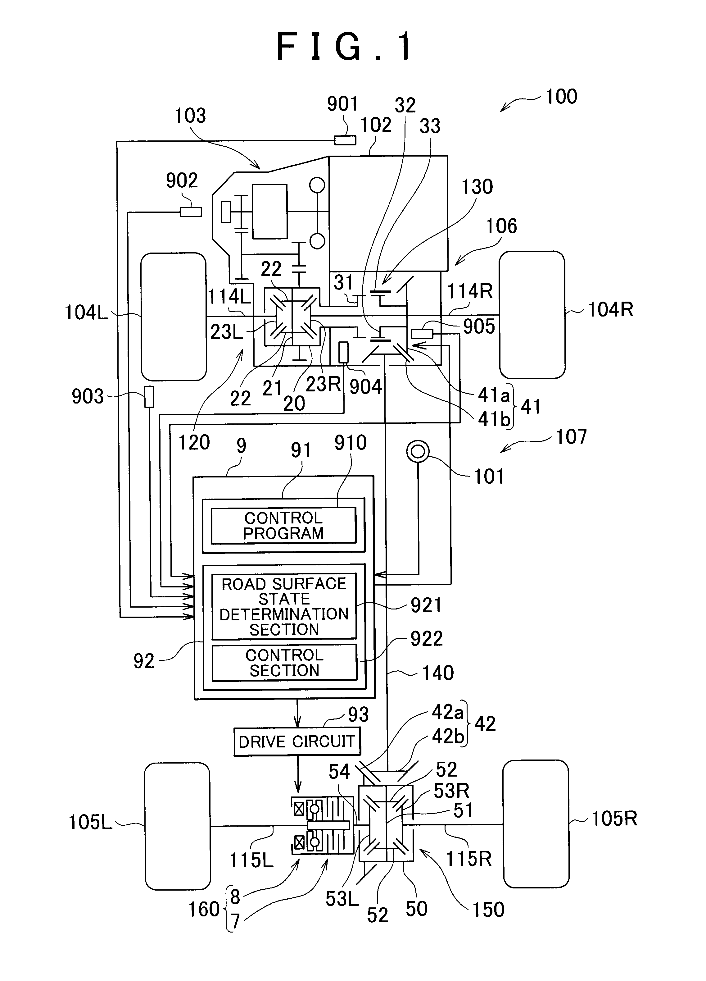
[0017]FIG. 1 is a schematic view illustrating an example of the configuration of a four-wheel-drive vehicle 100 according to an embodiment of the invention. The four-wheel-drive vehicle 100 includes an ignition switch 101, an engine 102, a transmission 103, a pair of right and left front wheels 104R, 104L, a pair of right and left rear wheels 105R, 105L, a first driving force transmission system 106, and a second driving force transmission system 107. The engine 102 is started in response to an operation of the ignition switch 101. The transmission 103 is a shifting device that changes the speed of rotation output from the engine 102. The first driving force transmission system 106 transmits the driving force output from the engine 102 to the front wheels 104R, 104L. The second driving force transmission system 107 transmits the driving force output from the engine 102 to the rear wheels 105R, 105L. The front wheels 104R, 104L are main drive wheels to which the driving force is alwa...


PUM


Abstract

A four-wheel-drive vehicle includes a first driving force transmission system and a second driving force transmission system. A control device controls the second driving force transmission system. The control device includes a road surface state determination section that determines whether a coefficient of friction of a road surface is equal to or higher than a predetermined value based on an index value regarding the coefficient of friction of the road surface, controls a dog clutch such that the dog clutch is engaged irrespective of the index value regarding the coefficient of friction of the road surface when an ignition switch is brought into the on-state, and controls the dog clutch such that the dog clutch is brought into the disengaged state when it is determined that the coefficient of friction of the road surface is equal to or higher than the predetermined value.

Description

INCORPORATION BY REFERENCE[0001]The disclosure of Japanese Patent Application No. 2012-250897 filed on Nov. 15, 2012 including the specification, drawings and abstract, is incorporated herein by reference in its entirety.BACKGROUND OF THE INVENTION[0002]1. Field of the Invention[0003]The invention relates to a four-wheel-drive vehicle.[0004]2. Description of Related Art[0005]There has been conventionally known a four-wheel-drive vehicle in which driving force is always transmitted from a drive source (engine) to a pair of right and left main drive wheels (front wheels) and driving force is transmitted from the drive source to a pair of right and left auxiliary drive wheels (rear wheels) via a plurality of clutches (refer to Japanese Patent Application Publication No. 2012-61923 (JP 2012-61923 A)).[0006]In the four-wheel-drive vehicle described in JP 2012-61923 A, a dog clutch is arranged between the drive source and a propeller shaft, which transmits driving force in the longitudina...

Claims


Application Information

Patent Timeline
IPC IPC(8): B60K23/08
CPCB60K23/08B60K17/344B60K17/35B60K23/0808B60K2023/0833B60K2023/0858B60W2540/06B60W2552/40
Inventor MITA, MASAKI
Owner JTEKT CORP
Why Eureka
Eureka Blog
Learn More