Dry ice blasting cleaning system and method of using the same

a cleaning system and dry ice blasting technology, applied in the direction of cleaning process and equipment, cleaning process using liquids, chemistry apparatus and processes, etc., can solve the problems of time-consuming, labor-intensive, and additional time for the box to dry, and achieve the effect of reducing labor intensity, reducing production costs, and improving efficiency

Inactive Publication Date: 2014-05-22
K B C GRP INC
View PDF20 Cites 5 Cited by
  • Summary
  • Abstract
  • Description
  • Claims
  • Application Information

AI Technical Summary

Problems solved by technology

While effective in cleaning the box, the process is time consuming, labor intensive, and requires additi

Method used


Image

  • Dry ice blasting cleaning system and method of using the same
  • Dry ice blasting cleaning system and method of using the same
  • Dry ice blasting cleaning system and method of using the same

Examples


Embodiment Construction

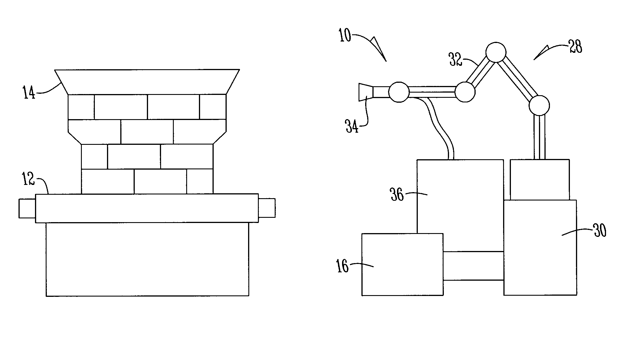
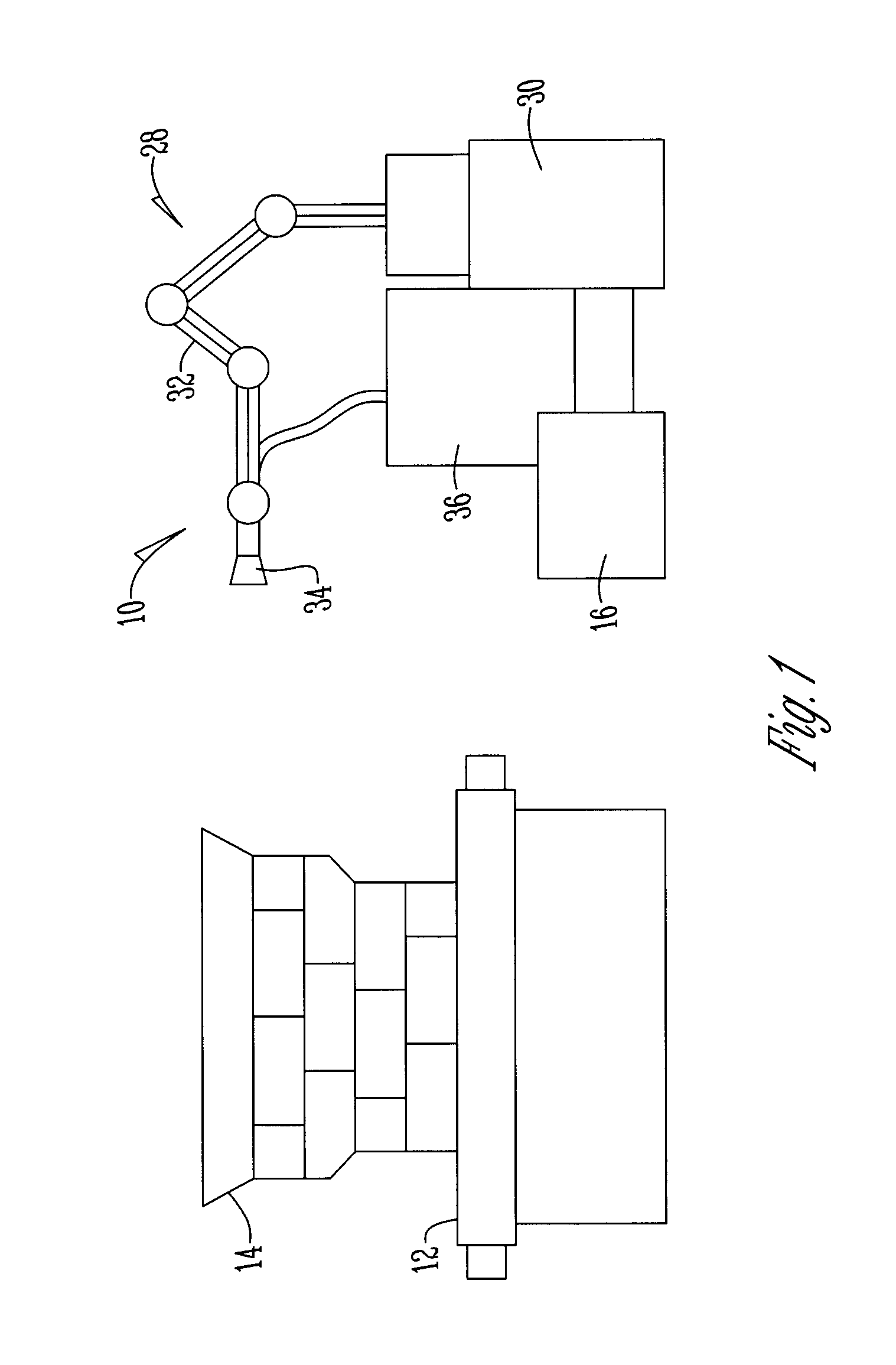
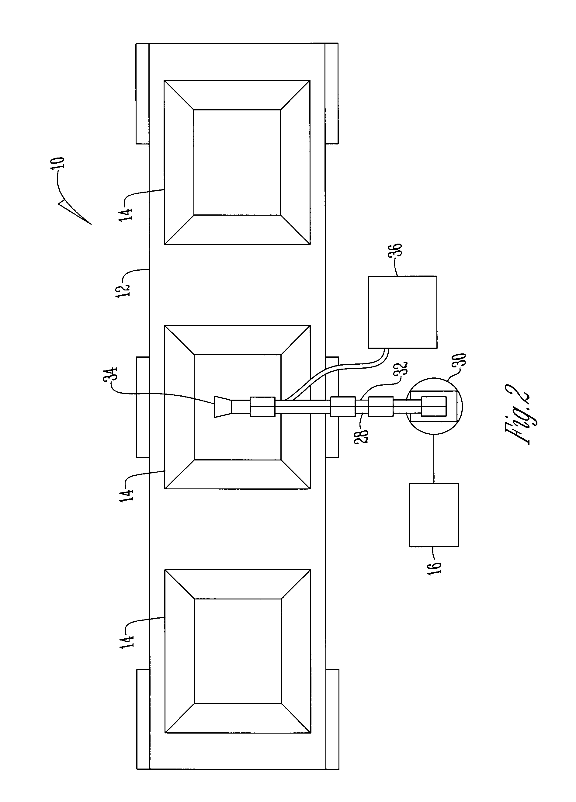
[0013]Referring to the Figures, the system 10 includes an assembly line 12 for transporting a product or device 14 to be cleaned. By example only, the device shown is a bulk seed tote box used for transporting seed. Other products and devices 14 may be used without departing from the invention.

[0014]The assembly line 12 is of any size or shape and preferably advancement of the device 14 along the assembly line 12 is operated by a controller 16. The controller includes a processor 18, a memory 20, software 22, a display 24, and an input device 26.

[0015]Positioned adjacent the assembly line 1 is a robot 28. The robot has a base 30 and an arm 32. Connected to the arm 32 is one or more nozzles 34 which are associated with C02 blasting equipment 36 for blasting granules of dry ice.

[0016]In operation, prior to loading a device 14 on the assembly line 12, the controller 16 is programmed to control the operation of the assembly line 12, the robot 28, and the C02 blasting equipment 36. More ...


PUM

PropertyMeasurementUnit
Dimensionless propertyaaaaaaaaaa

Abstract

A cleaning system having at least one C02 blasting nozzle connected to a robotic arm to automatically and selectively clean an object transported on an assembly line.

Description

BACKGROUND OF THE INVENTION[0001]This invention is directed toward a dry ice blasting cleaning system, and more particularly a cleaning system that utilizes a robotic arm to clean a device being transported on an assembly line.[0002]Cleaning systems are well-known in the art. As an example, in the bulk-seed industry, tote boxes are cleaned manually with water using a high pressure nozzle. While effective in cleaning the box, the process is time consuming, labor intensive, and requires additional time for the boxes to dry. In addition, because the boxes sometimes contain chemicals, the water needs to be filtered and / or treated before disposal or further use.[0003]Other cleaning systems have utilized C02 (or dry ice) blasting equipment. Typically, this equipment is operated manually or through use of a robotic device designed to clean a specific object. These devices are complex, expensive to manufacture, and have limited use. Accordingly, there is a need in the art for a system that ...

Claims


Application Information

Patent Timeline
IPC IPC(8): B08B5/02
CPCB08B9/093B24C1/003
Inventor JOHNSTON, THOMAS R.DAVIS, CURT MATHEW
Owner K B C GRP INC
Why Eureka
Try Eureka