Motor vehicle light with a light conductor and a shield that is visible through the light conductor

Inactive Publication Date: 2014-05-22
AUTOMOTIVE LIGHTING REUTLINGEN GMBH
View PDF6 Cites 28 Cited by
  • Summary
  • Abstract
  • Description
  • Claims
  • Application Information

AI Technical Summary

Benefits of technology

[0009]Because the shield is realized as a non-reflecting shield, very little incident sunlight is correspondingly reflected. Consequently, the signal color of the light will be changed less in bright environments than would be otherwise the case with a metallized, colored shield. This results in a high signal effect (particularly for a flashing light) even during insolation. Moreover, this will prevent so-called phantom light effects (where incident sunlight in the light is reflected so awkwardly that it is misinterpreted as a signal by another road user). Further, this results in lower costs result compared to lights with a reflecting shield, since no aluminizing is necessary.
[0010]Because the first side has individual decoupling surfaces which are spatially separated from each other and are offset relative to each other in the principal emission direction, and that the deflection surfaces lying in the second side are also offset in relation to each other in the principal emission direction, wherein the decoupling surfaces and the deflection surfaces are matched to each other and are dimensioned and arranged such that in each case one of the decoupling surfaces in each case is illuminated only from one deflection surface from the second side. This results in a flat light conductor area which permits the light to be emitted approximately in the direction of the normal to the surface of the first side, which has a wide and expanded surface compared to the narrow sides of the light conductor. The result is a comparatively large light emitting surface with a comparatively small light conductor volume that is irradiated with light. As a consequence, the losses due to absorption are lower th

Problems solved by technology

This results in a high signal effect (particularly for a flashing light) even during insolati

Method used


Image

  • Motor vehicle light with a light conductor and a shield that is visible through the light conductor
  • Motor vehicle light with a light conductor and a shield that is visible through the light conductor
  • Motor vehicle light with a light conductor and a shield that is visible through the light conductor

Examples


Embodiment Construction

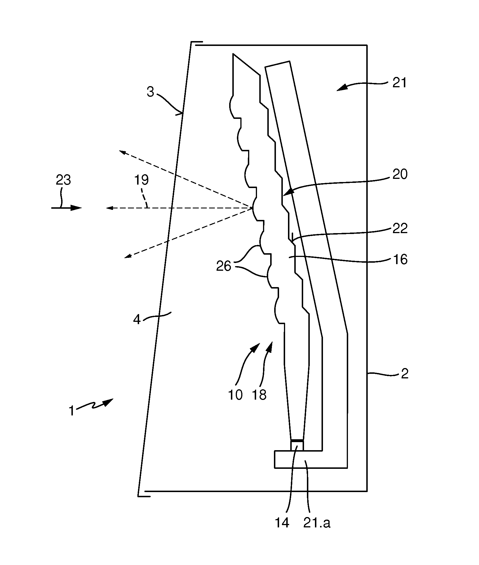
[0028]FIG. 1 shows a motor vehicle light 1 with a housing 2 and a transparent cover plate 3, which covers a light outlet opening 4 of the light. The light includes a light conductor 10 and a light source 14, which are arranged in relation to one another so that light of the light source will be coupled into the light conductor.

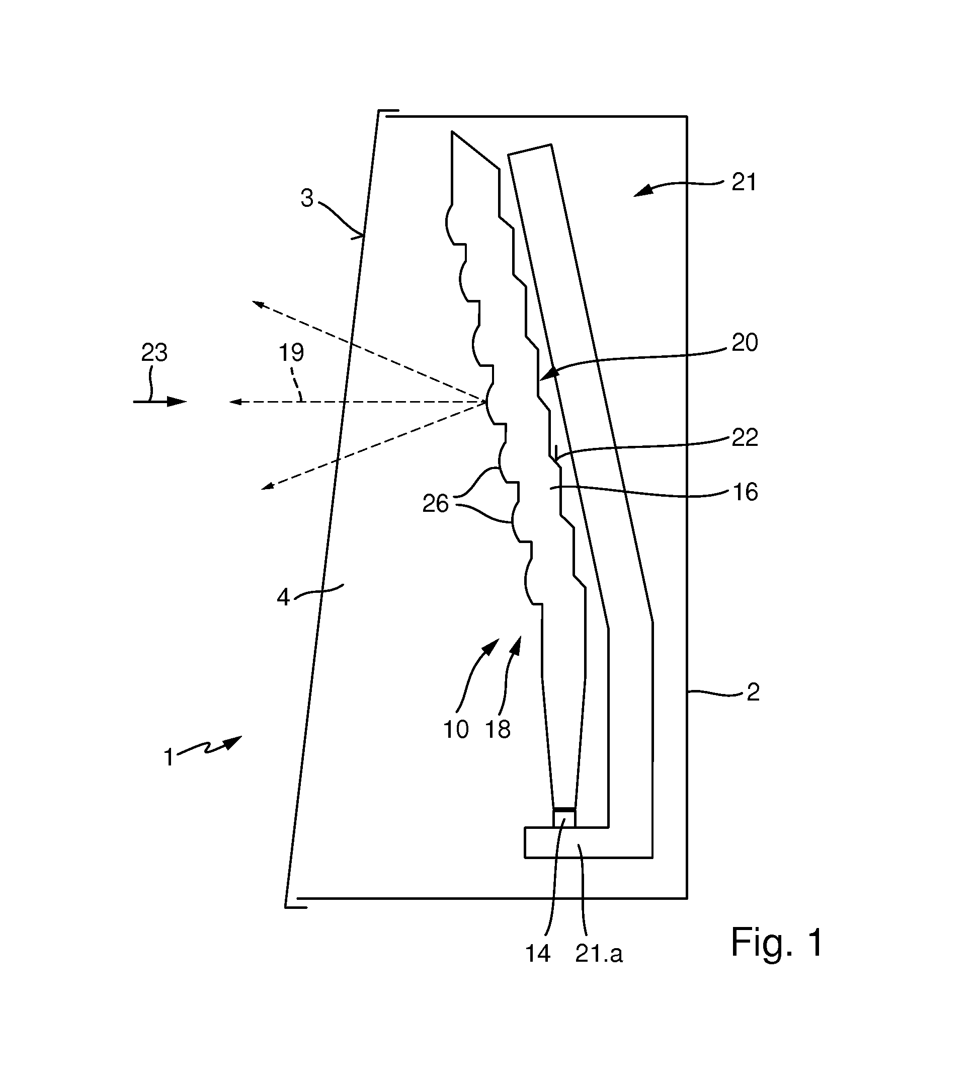
[0029]The light conductor includes a first side 18 and a second side 20 which lies opposite the first side. The first side and the second side border a decoupling volume 16 of the light conductor, wherein the second side includes deflection surfaces 22 which are set up to deflect incident light toward the first side 18 such that light is decoupled there around a principal emission direction 19. The motor vehicle light further includes a shield 21 that is arranged behind the second side 20 in a direction 23 opposite to the principal emission direction 19. The shield 21 is a non-reflecting shield which appears black. In one embodiment, the black shield is design...


PUM


Abstract

Presented is a motor vehicle light with a light source, a light conductor, which comprises a bordering decoupling volume opposite of a first side and a second side lying opposite the second side, wherein the second side comprises decoupling elements, which decouple light distributed about a principal propagation direction, and wherein the motor vehicle light comprises a colored shield which is positioned behind the second side in a direction opposite to the principal propagation direction. The shield is a black shield.

Description

CROSS-REFERENCE TO RELATED APPLICATION[0001]This application is based upon and claims priority to published German Patent Application 10 2012 221 389.9, filed on Nov. 22, 2012.BACKGROUND OF INVENTION[0002]1. Field of the Invention[0003]The present invention relates to a motor vehicle light.[0004]2. Description of the Related Art[0005]Motor vehicle lights are known in the art. For example, published German Patent Application DE 197 40 317 C1 discloses a light source and a light conductor which includes a decoupling volume that is bordered from a first side and a second side opposite the first side. The second side includes deflection surfaces for diverting incident light toward the first side such that the light is decoupled, and is distributed about a principal emission direction. The light further includes a shield that is arranged behind the second side in a direction opposite to the principal emission direction. The shield is a colored shield and determines the color of the motor...

Claims


Application Information

Patent Timeline
IPC IPC(8): B60Q1/26F21W107/10
CPCF21S43/237F21S43/241F21S43/245F21S43/249F21S43/247F21S43/315B60Q1/26
Inventor ZWICK, HUBERT
Owner AUTOMOTIVE LIGHTING REUTLINGEN GMBH
Why Eureka
Try Eureka