Antenna arrangement for 3g/4g svlte and MIMO to enable thin narrow boardered display phones

a thin phone and display phone technology, applied in diversity/multi-antenna systems, independent non-interacting antenna combinations, spatial transmit diversity, etc., can solve the problem that large filters or even smaller filters cannot be packed in a thin phone design, the specific absorption rate is higher, and the receiver is not sensitive enough to the high level of receiver desensitization

Active Publication Date: 2014-05-22
GOOGLE TECH HLDG LLC
View PDF4 Cites 29 Cited by
  • Summary
  • Abstract
  • Description
  • Claims
  • Application Information

AI Technical Summary

Problems solved by technology

These high levels of receiver desensitization present a serious challenge to designers of wireless communication devices.
Furthermore, designers are challenged to provide acceptable levels of LTE multiple input multiple output (MIMO) performance by utilizing LTE receive antennas that are not correlated.
The large filter or even the smaller filters cannot be packed in a thin phone design.
However, having a transmit antenna at the top of the phone results in higher Specific Absorption Rate (SAR) and poor “Phantom” Performance.
SAR compliance is generally challenging with multiple antenna / transmitters in phones.
Having a transmit antenna at the top or upper side (even if combined with a bottom antenna element) still has significant SAR issues in a thin phone.
Also, Phantom performance is worse when the antenna is placed at the top or the side of the device than when the antenna is positioned at the bottom of the device.
Furthermore, having portions of the main antenna elements on the bottom sides of the phones make the antenna elements more susceptible to significant hand detuning / loading “variation” effects in natural hand holding talk positions than having antenna elements entirely confined to the bottom.

Method used


Image

  • Antenna arrangement for 3g/4g svlte and MIMO to enable thin narrow boardered display phones
  • Antenna arrangement for 3g/4g svlte and MIMO to enable thin narrow boardered display phones
  • Antenna arrangement for 3g/4g svlte and MIMO to enable thin narrow boardered display phones

Examples


Embodiment Construction

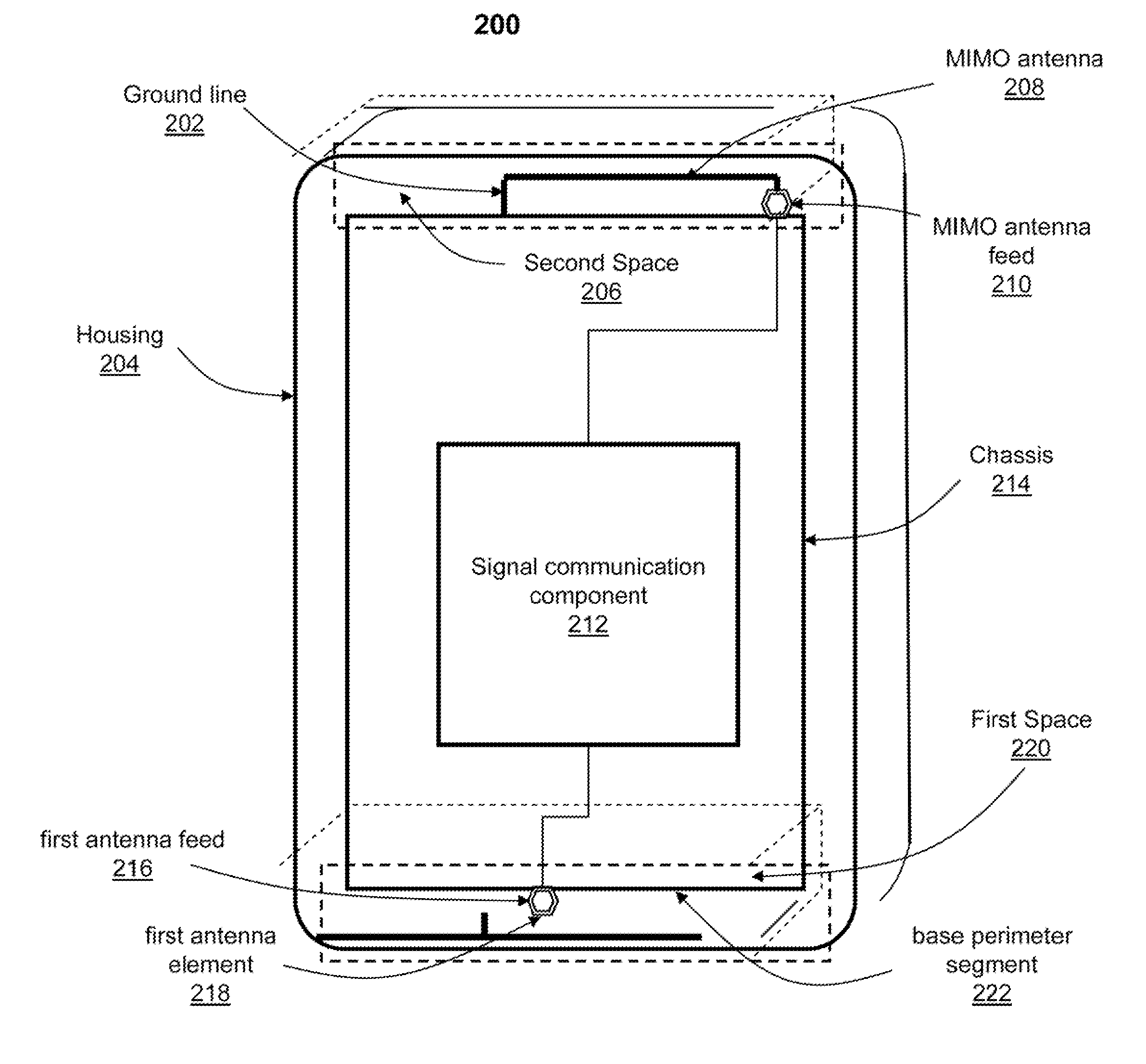
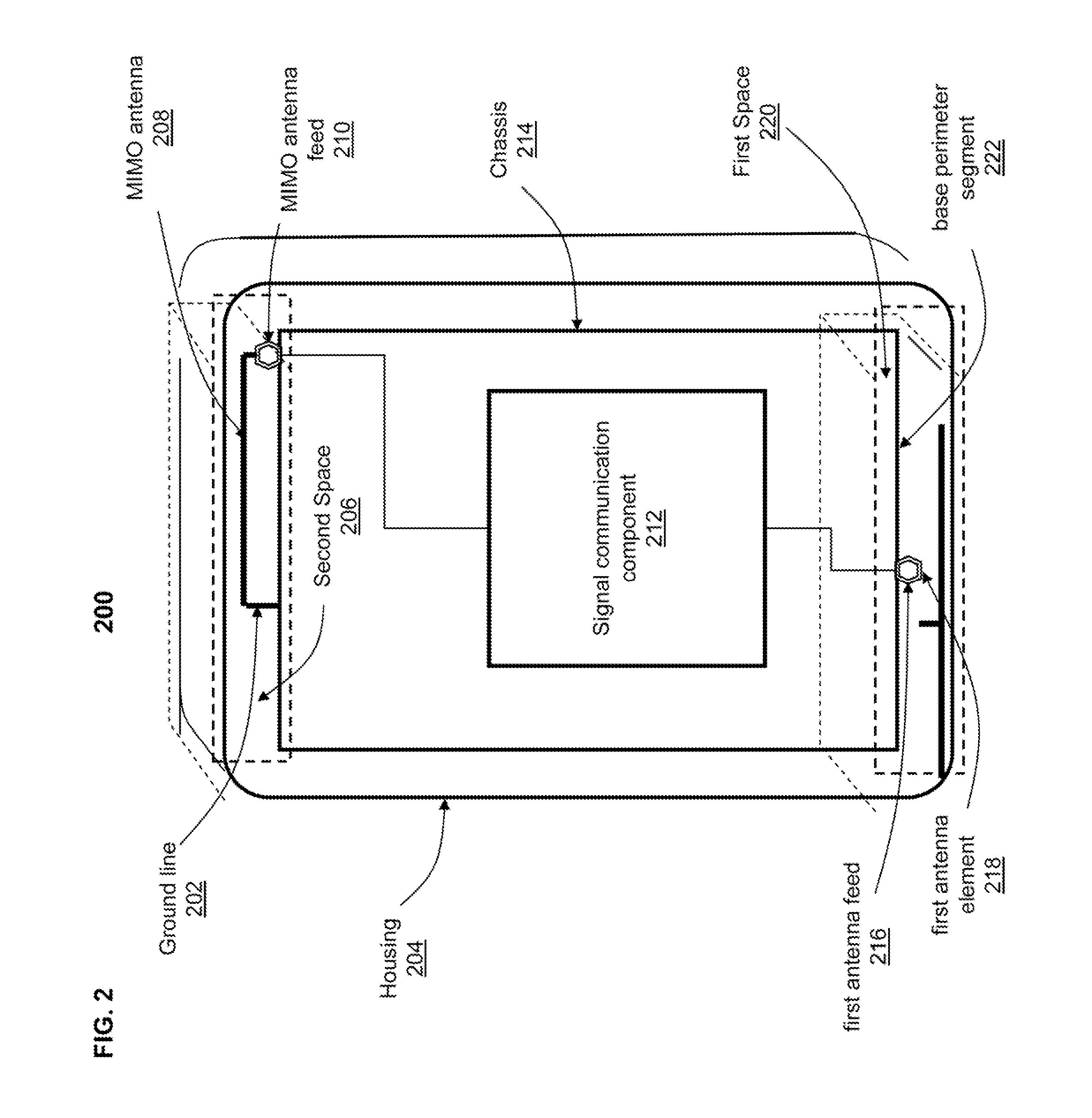
[0019]The illustrative embodiments provide a method and system for providing a multiple input multiple output (MIMO) antenna arrangement in a wireless communication device. A first antenna element and a second antenna element co-located within a same antenna volume are respectively coupled to first and second antenna feeds proximate to a base perimeter segment of a device chassis. The first antenna feed is positioned at a pre-calculated distance from the second antenna feed. The second antenna element, designated as a first MIMO antenna, is coupled to an antenna ground positioned proximate to the first antenna feed and at a pre-determined distance from the second antenna feed. A second MIMO antenna is placed proximate to a top perimeter segment of the device chassis. The antenna arrangement achieves (a) low correlation between the first MIMO antenna and the second MIMO antenna, (b) an acceptable or pre-determined level of antenna isolation between the first antenna element and the s...


PUM


Abstract

A method and system provides a multiple input multiple output (MIMO) antenna arrangement in a wireless communication device. A first antenna element and a second antenna element co-located within a same antenna volume are respectively coupled to first and second antenna feeds proximate to a base perimeter segment of a device chassis. The first antenna feed is at a pre-calculated distance from the second antenna feed. The second antenna element, a first MIMO antenna, is coupled to an antenna ground positioned proximate to the first antenna feed and at a pre-determined distance from the second antenna feed. A third antenna element operating as a second MIMO antenna is placed proximate to a top perimeter segment of the device chassis. The antenna arrangement achieves (a) low correlation between the MIMO antennas and (b) an acceptable or pre-determined level of antenna isolation between the first antenna element and the second antenna element.

Description

BACKGROUND[0001]1. Technical Field[0002]The present disclosure relates in general to wireless communication devices and in particular to antenna arrangements in wireless communication devices.[0003]2. Description of the Related Art[0004]With the rapid deployment of Long Term Evolution (LTE) Fourth Generation (4G) networks, an increasing number of wireless communication providers are implementing Simultaneous Voice and LTE (SVLTE) data technologies. For example, voice communication within SVLTE is supported using Third Generation and / or Code Division Multiple Access (CDMA) technologies and data communication is provided using 4G technologies, which can be supported in more recently designed smart-phones.[0005]While providing SVLTE communication (e.g., by using LTE Band 13 and the CDMA850 band), wireless communication devices can experience high levels of desensitization of receivers in select channels of CDMA850 and LTE Band 13. These high levels of receiver desensitization present a...

Claims


Application Information

Patent Timeline
Patent Type & Authority Applications(United States)
IPC IPC(8): H01Q21/28H04B1/44H01Q5/00H04B7/04
CPCH01Q5/0003H01Q21/28H04B7/0413H04B1/44H01Q1/243
Inventor ABUDUL-GAFFOOR, MOHAMMED R.ABEDIN, MD FAISALDUONG, MINH H.
Owner GOOGLE TECH HLDG LLC
Why Eureka
Try Eureka