Vehicular Door Handle Assembly With Inertial Secondary Catch Position

a technology of secondary catch position and vehicle door handle, which is applied in the direction of mechanical equipment, fastening means, and applications for locking, etc., can solve the problem of bypassing the primary catch point of the locking mechanism

Inactive Publication Date: 2014-05-29
HUF NORTH AMERICA AUTOMOTIVE PARTS MFG
View PDF25 Cites 29 Cited by
  • Summary
  • Abstract
  • Description
  • Claims
  • Application Information

AI Technical Summary

Benefits of technology

[0007]A general objective of the present invention is to provide an outer door handle assembly for a vehicle including a base, a latch release mechanism, and an inertial catch. The latch release mechanism includes a countermass assembly with a primary catch point and a secondary catch point, and the latch release mechanism and the counterassembly rotate about a first shaft coupled to the base between a rest position and an active position in response to movement of a door handle. The inertial catch includes a blocking shoulder and rotates about a second shaft coupled to the base from an unblocking position to a blocking position in response to inertia forces acting upon the inertial catch. The inertial catch prevents the countermass assembly from rotating into its active position by the blocking shoulder engaging the primary catch point or the secondary catch point when the inertial catch is in its blocking position.
[0008]According to another objective of the present invention, a locking mechanism for a door handle assembly includes a countermass assembly and an inertial catch. The countermass assembly includes a primary catch point and a secondary catch point, and rotates between a rest position and an active position. The inertial catch includes a blocking shoulder and rotates between an unblocking position and a blocking position. The inertial catch is positioned relative to the countermass assembly so that, when the inertial catch is rotated to its blocking position, the inertial catch prevents the countermass assembly from rotating into its active position.

Problems solved by technology

However, some inertial and / or deformation-induced forces, such as those caused by high-acceleration impact or rollover crash events, may cause the locking mechanism to bypass the primary catch point.

Method used


Image

  • Vehicular Door Handle Assembly With Inertial Secondary Catch Position
  • Vehicular Door Handle Assembly With Inertial Secondary Catch Position
  • Vehicular Door Handle Assembly With Inertial Secondary Catch Position

Examples


Embodiment Construction

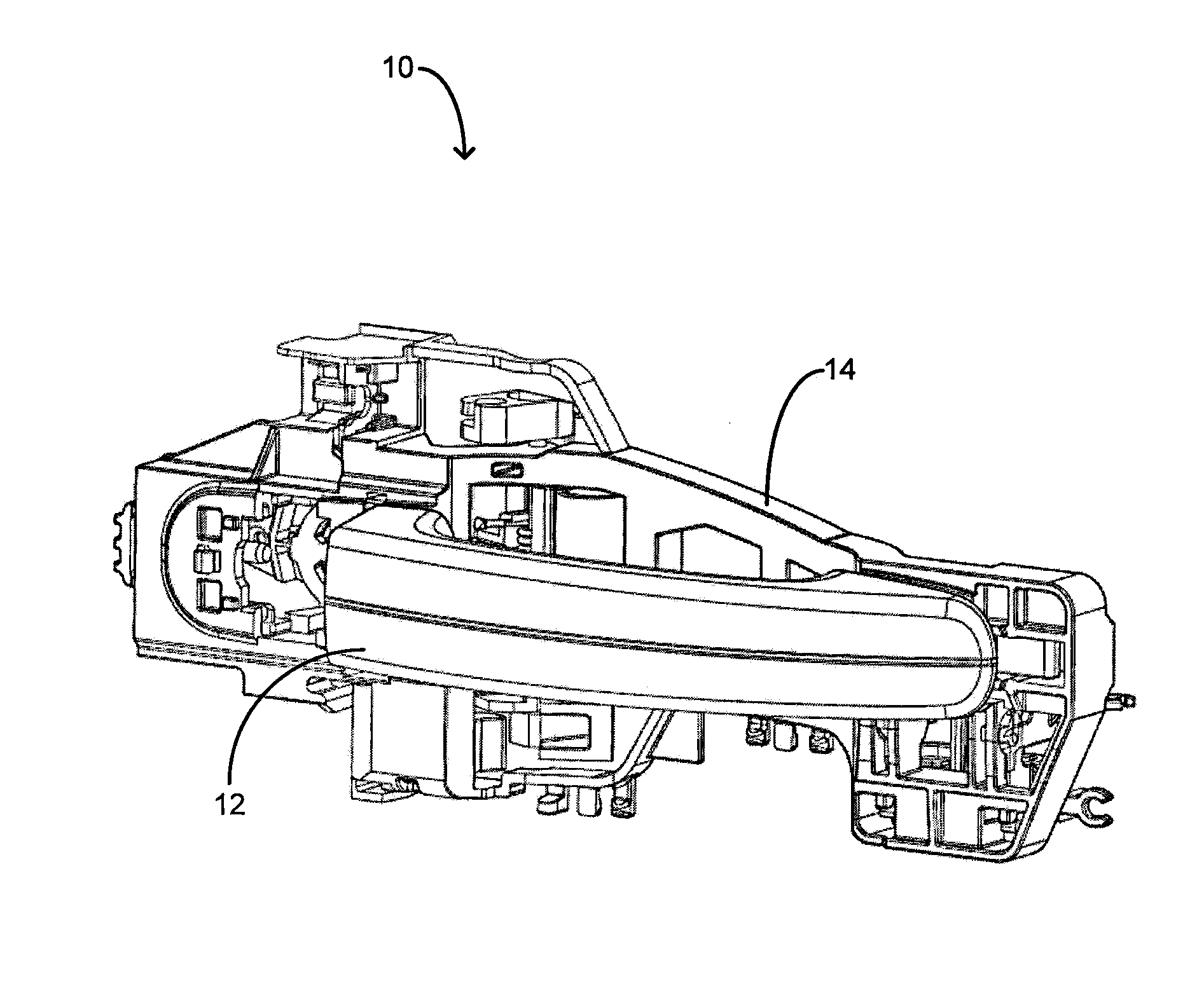
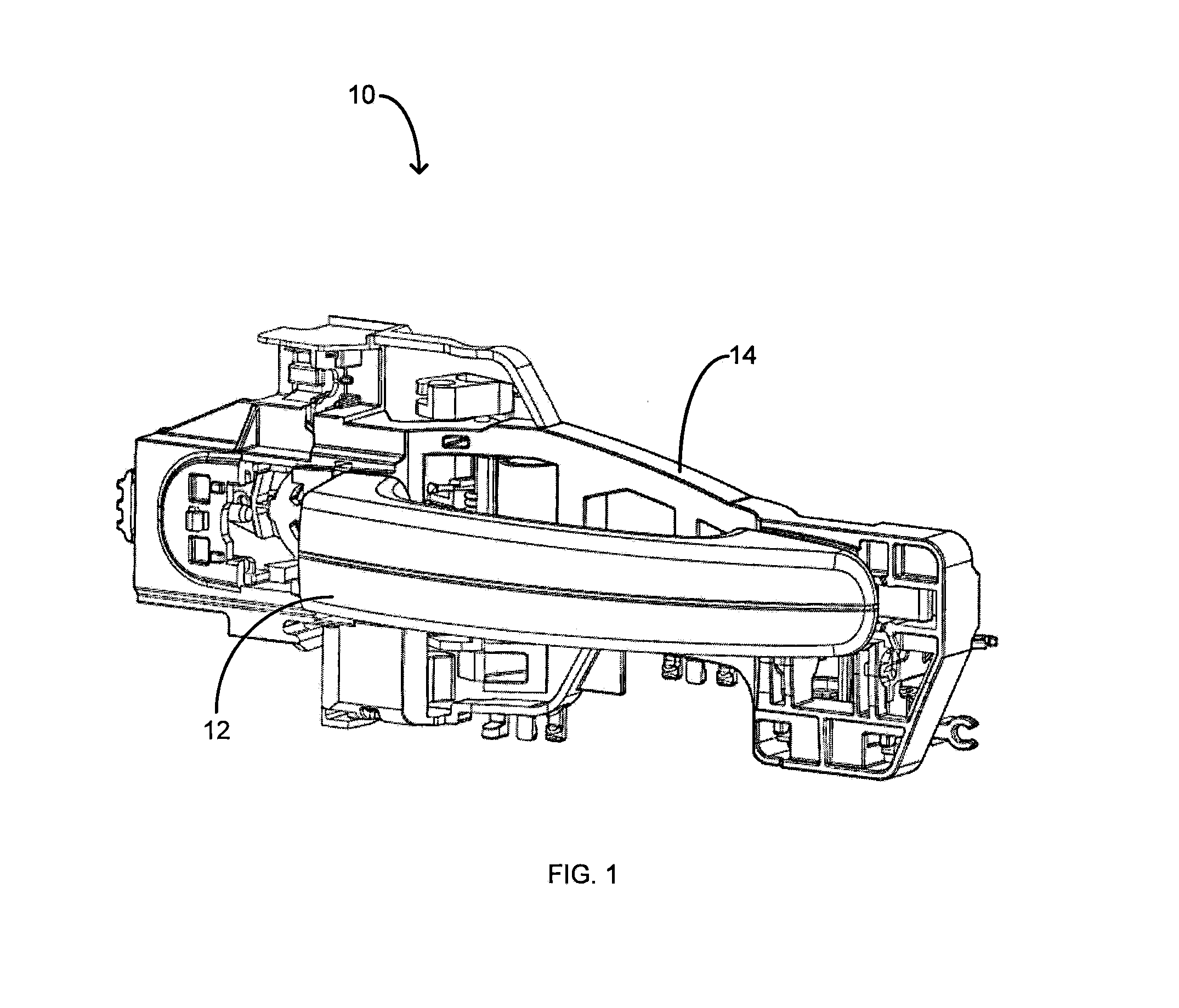
[0017]The present invention provides a vehicle outer door handle assembly with a latch release mechanism that includes primary and secondary catch points to prevent unintentional opening of the vehicle door in the event of a vehicle crash. During some crash events, forces cause a countermass assembly and an inertial block of the vehicle door handle assembly to move relative to each other so that the countermass assembly and the inertial block contact each other at the primary catch point to prevent actuation of the latch release mechanism. During other crash events, however, forces may cause the countermass assembly to move relative to the inertial mass in a way that bypasses the primary catch point contact. Although this primary catch point contact is bypassed, the countermass assembly and the inertial block still contact each other at the secondary catch point to prevent actuation of the latch release mechanism

[0018]FIG. 1 illustrates a vehicle outer door handle assembly 10, accor...


PUM


Abstract

A vehicle outer door handle assembly includes a base, a latch release mechanism, and an inertial catch. The latch release mechanism includes a countermass assembly with a primary catch point and a secondary catch point, and the latch release mechanism and the counterassembly rotate between a rest position and an active position in response to movement of a door handle. The inertial catch includes a blocking shoulder and rotates from an unblocking position to a blocking position in response to inertia forces acting upon the inertial catch. When the inertial catch is in its blocking position, it prevents the countermass assembly from rotating into its active position by the blocking shoulder engaging the primary catch point or the secondary catch point.

Description

CROSS REFERENCE TO RELATED APPLICATIONS [0001]None.STATEMENT REGARDING FEDERALLY SPONSORED RESEARCH[0002]Not Applicable.BACKGROUND OF THE INVENTION[0003]The present invention relates to an outer door handle assembly for a motor vehicle. More specifically, the present invention relates to a locking mechanism of an outer door handle assembly for preventing door latch release during crash-induced door handle movement.[0004]Motor vehicles include at least one outer door handle for releasing a door latch mechanism in order to open a vehicle door. Typically, a user actuates the outside door handle by activating a handle portion relative to a base. The handle portion may, however, also be activated when the outside door handle experiences a high inertia force, such as that caused by a vehicle crash. The movement of the handle portion relative to the base in response to the high inertia force can cause inadvertent unlatching and resultant opening of the door. This is undesirable during cras...

Claims


Application Information

Patent Timeline
Patent Type & Authority Applications(United States)
IPC IPC(8): E05B65/12
CPCE05B77/06E05B85/16Y10T292/57
Inventor DA DEPPO, LYNN D.KAMAL, EHAB
Owner HUF NORTH AMERICA AUTOMOTIVE PARTS MFG
Why Eureka
Try Eureka