Device and method for detecting moving objects

a detection device and moving object technology, applied in the field of moving object detection apparatus and method, can solve the problems of not being able to detect the motion vector (moving object, not being able to detect the movement vector), and not being able to detect the moving object in the image, so as to maintain the detection accuracy of a slow moving object

Active Publication Date: 2014-05-29
FUJIFILM CORP
View PDF20 Cites 10 Cited by
  • Summary
  • Abstract
  • Description
  • Claims
  • Application Information

AI Technical Summary

Benefits of technology

[0008]The present invention is made in view of such conditions and it is an object to provide a moving object detection apparatus and method that can detect a moving object even if the moving object is fast, while maintaining the detection accuracy of a slow moving object.
[0013]That is, the moving object detection by the first moving object detection device and the moving object detection by the second moving object detection device are performed in parallel. At this time, the first time interval at which the first moving object detection device performs moving object detection is set longer than the second time interval at which the second moving object detection device performs moving object detection. This is because the processing data amount by the motion vector calculation device is greater than the processing data amount by the difference image generation device and requires much time to calculate a motion vector. Subsequently, the integration device integrates the latest detection result by the first moving object detection device and the latest detection result by the second moving object detection device. Although an object requiring the real time performance is a fast moving object, the real time performance can be secured by shortening the second time interval of the moving object detection by the second moving object detection device.
[0014]In the moving object detection apparatus according to another aspect of the present invention, it is preferable that the difference image generation device generates a difference image between reduction images acquired by reducing the two images. By this means, it is possible to intend the shortening of the processing time to generate the difference image, and enhance the responsiveness to a fast moving object.
[0015]In the moving object detection apparatus according to another aspect of the present invention, the motion vector calculation device includes a feature point extraction device for extracting a plurality of feature points from one image of the two images with the different imaging times and a corresponding point detection device for detecting a plurality of corresponding points that correspond to the plurality of feature points of the one image on the other image of the two images, and calculates motion vectors that connect the plurality of feature points of the one image and the corresponding points of the other image that correspond to the plurality of feature points. By this means, it is possible to detect a moving object (a region and motion vector of the moving object) accurately.
[0021]Whether time-series images are acquired at the time of panning or the time-series images are acquired at the time of non-panning is determined. Therefore, in a case where a moving object candidate region is extracted at the time of non-panning, the moving object candidate region can be determined to be a moving object region. Here, since the moving object candidate region is extracted by an inter-frame difference images, it is possible to extract even a fast moving object as a moving object candidate region, and, in the case of a slow moving object, it is possible to detect a moving object accurately by calculating a motion vector.
[0047]According to the present invention, since moving object detection by a motion vector and moving object detection by a difference image between frames are used together and moving object detection is performed by integrating these detection results, it is possible to detect a fast moving object that cannot be subjected to the moving object detection by the motion vector while maintaining the detection accuracy of a slow moving object.

Problems solved by technology

However, in the invention described in PTL 1, since a moving object is detected on the basis of a motion vector, there is a problem that it is not possible to detect a moving object in an image due to an object blur in the case of a fast moving object, and, as a result, it is not possible to detect the motion vector (moving object).
That is, in a case where the speed of the object is fast, since the object blur occurs, it is not possible to extract a feature point and corresponding point that are the starting point and ending point of the motion vector (it is not possible to detect the motion vector).
Moreover, the calculation cost of the motion vector is high, and it is difficult to balance the real time performance and the elaborateness.

Method used


Image

  • Device and method for detecting moving objects
  • Device and method for detecting moving objects
  • Device and method for detecting moving objects

Examples


first embodiment

[0092]FIG. 5 is a flowchart showing the first embodiment of a moving object detection method according to the present invention.

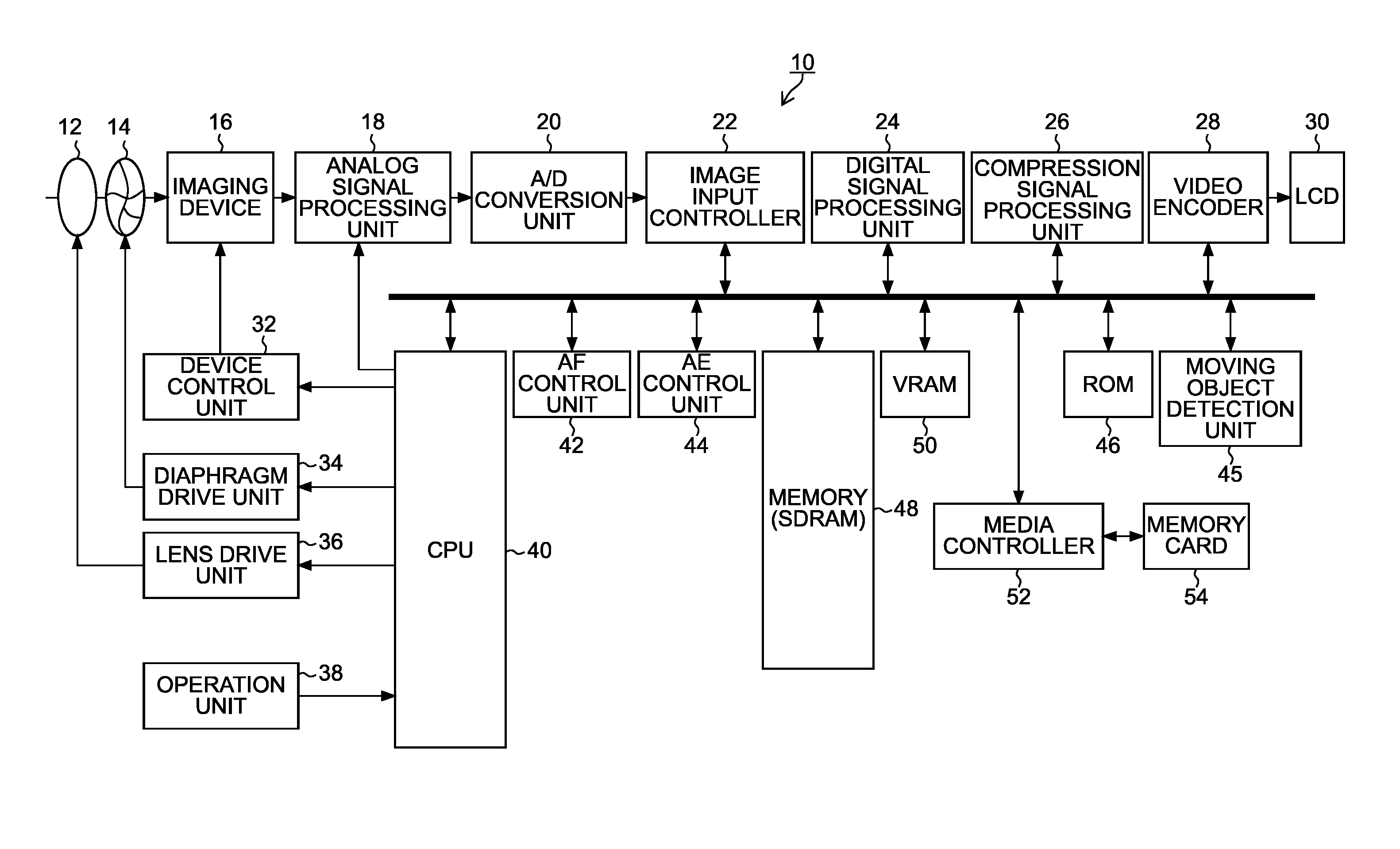
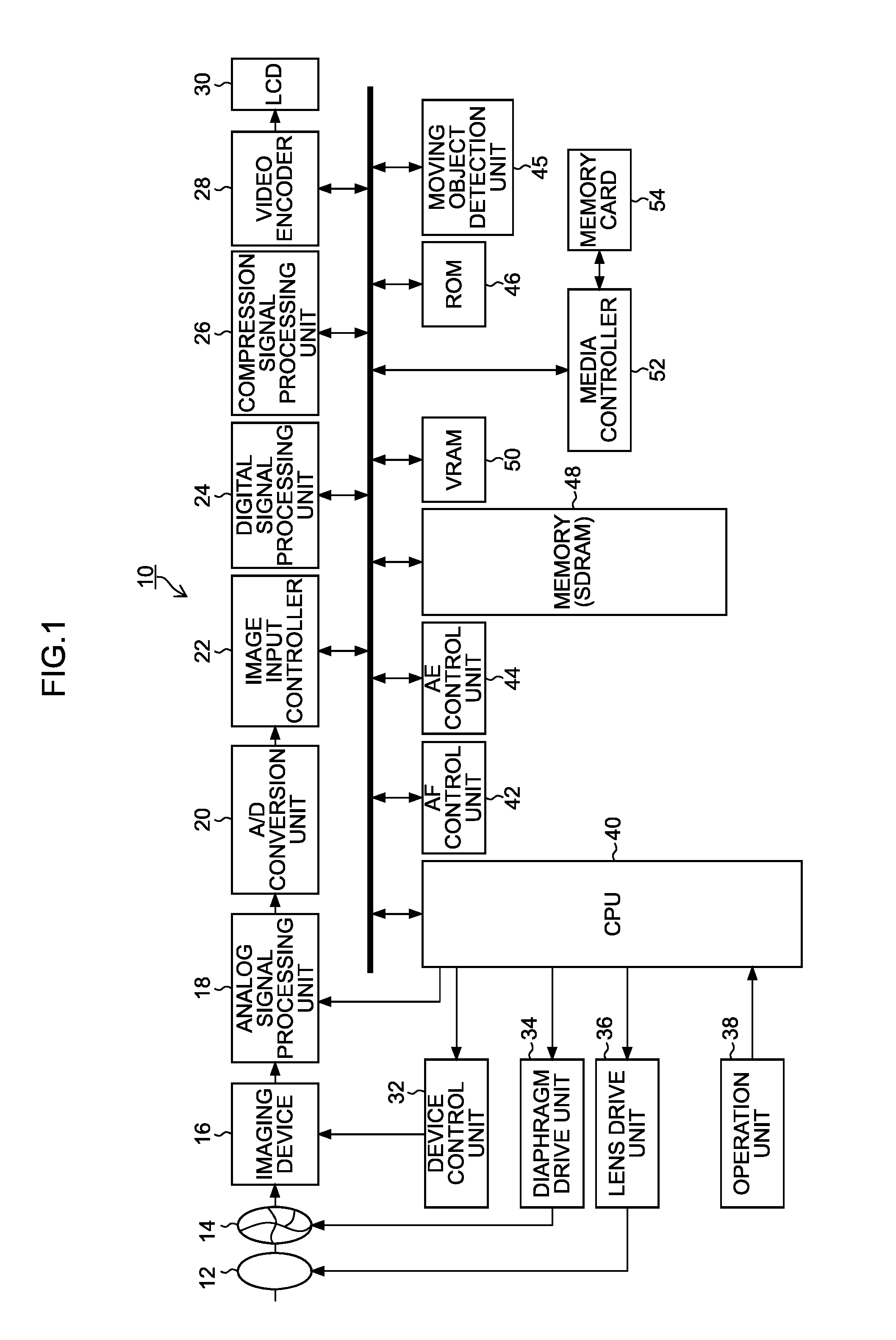
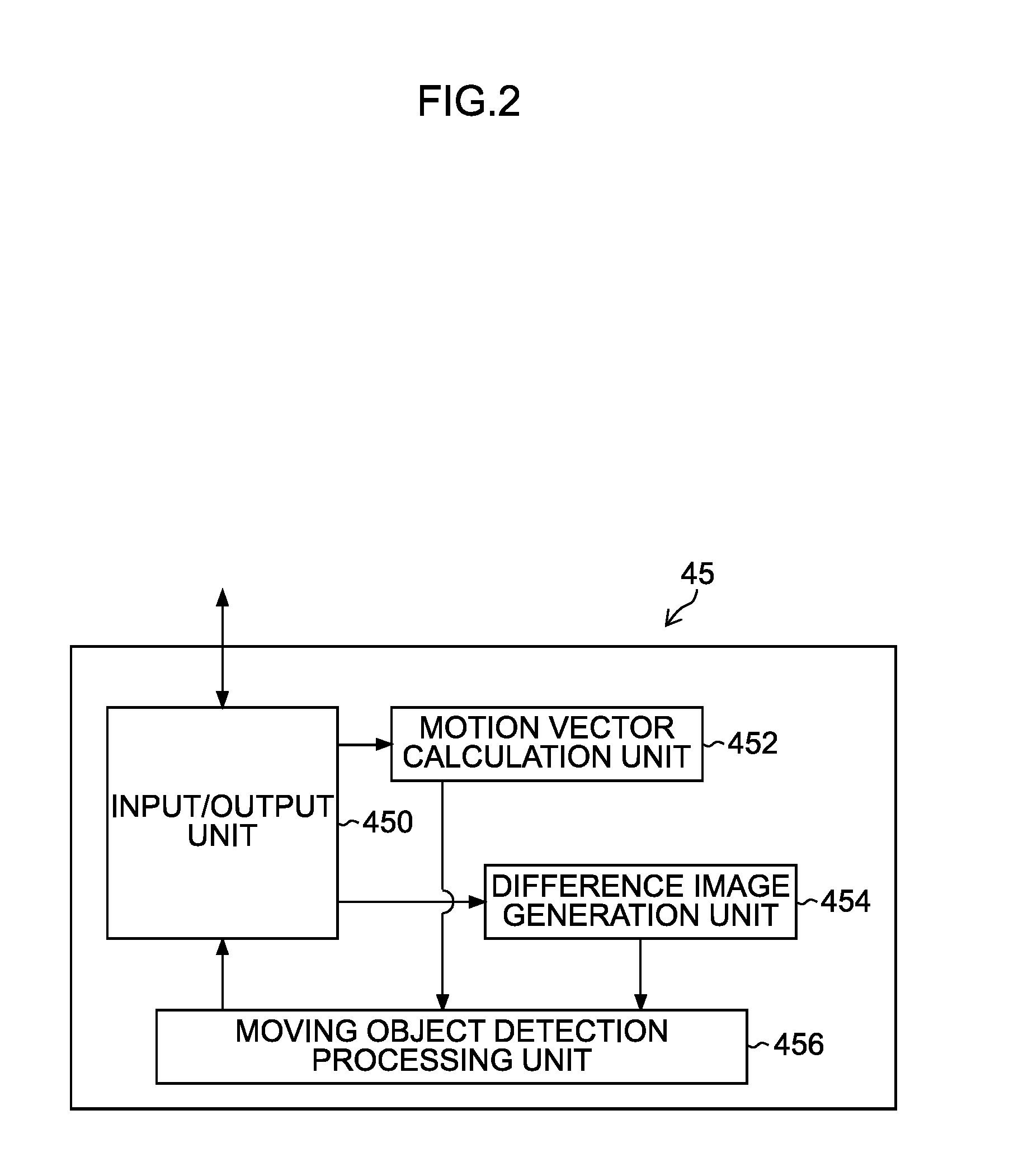
[0093]First, the input / output unit 450 of the moving object detection unit 45 illustrated in FIG. 2 inputs two images with different imaging times (image pair: adjacent frames are desirable) during imaging of a live view image or moving image (step S10). The motion vector calculation unit 452 calculates the motion vector of each feature point on the basis of detection of multiple feature points and corresponding points on the two input images (step S12). The moving object detection processing unit 456 detects a moving object (moving object region) on the basis of the calculated motion vectors (step S14).

[0094]Meanwhile, the difference image generation unit 454 generates a difference image from the image pair input in step S10 (step S16), and the moving object detection processing unit456 detects a moving object (moving object region) by the generated differ...

second embodiment

[0103]FIG. 7 is a flowchart showing the second embodiment of a moving object detection method according to the present invention. Here, the same step numbers are attached to the common parts with the first embodiment illustrated in FIG. 5 and their detailed explanation is omitted.

[0104]As compared with the first embodiment, the second embodiment illustrated in FIG. 7 has main features that the moving object detection by the motion vector and the moving object detection by the inter-frame difference are processed in parallel and that the processing times of both moving object detection are different and the time of one moving object detection by the motion vector is longer than the time of one moving object detection by the inter-frame difference.

[0105]In general, the motion vector calculation has a high calculation cost and it is difficult to balance the real time performance and the elaborateness of the detection. For example, although it is possible to perform moving object detect...

third embodiment

[0113]FIG. 8 is a flowchart showing the third embodiment of a moving object detection method according to the present invention.

[0114]First, two images with different imaging times (image pair) are input during imaging of a live view image or moving image (step S30). The difference image generation unit 454 generates a difference image from the image pair input in step S30 (step S32), and the moving object detection processing unit 456 extracts a moving object candidate region by the generated difference image between frames (step S34).

[0115]Here, it is set as the moving object candidate region because, although the difference region is nearly equal to the moving object region in the case of a fixed camera, since there is a difference even by camera movement in the case of a non-fixed camera, there is a possibility that the difference region differs from the moving object region, and, in the case of panning, the difference region is caused even if the moving object is not present.

[0...


PUM


Abstract

A moving object detection apparatus comprising: an image acquisition device; a first moving object detection device; a difference image generation device; a second moving object detection device for detecting existence / nonexistence of the moving object based on the difference image generated by the difference image generation device; and an integration device for integrating a detection result by the first moving object detection device and a detection result by the second moving object detection device and determining that the moving object is detected in a case where the moving object is not detected by at least the first moving object detection device and the moving object is detected by the second moving object detection device.

Description

BACKGROUND OF THE INVENTION[0001]1. Field of the Invention[0002]The present invention relates to a moving object detection apparatus and method, and specifically relates to a technique that detects a moving object from frame images continuously taken.[0003]2. Description of the Related Art[0004]In the related art, there is suggested an image motion vector detection apparatus that performs moving object detection by detecting a camera-shake vector from an imaging signal acquired in a video camera and detecting an image motion vector which indicates the motion of an object and which can be distinguished from the camera-shake vector (PTL 1: Japanese Patent Application Laid-Open No. 6-217188).[0005]Moreover, there is suggested a moving object monitoring apparatus that calculates an inter-frame difference from frame images taken by a television camera and detects a moving object from the inter-frame difference (PTL 2: Japanese Patent Application Laid-Open No. 5-183901). Especially, this ...

Claims


Application Information

Patent Timeline
Patent Type & Authority Applications(United States)
IPC IPC(8): G06T7/20G06K9/00
CPCG06T2207/10016G06T2207/10144G06T2207/20201G06T7/246G06T7/254H04N23/673H04N23/6815H04N23/6811H04N23/631G06T2207/20212G06T7/20
Inventor ENDO, HISASHI
Owner FUJIFILM CORP
Why Eureka
Try Eureka