Range detection device

a detection device and range technology, applied in the direction of magnetic measurement, mechanical equipment, instruments, etc., can solve the problems of difficult to remove air bubbles thoroughly, increase equipment cost, and damage to substrate and magnetic detection elements, so as to improve reliability, reduce stress concentration at the solder connection portion between the substrate and the magnetic detection element, and facilitate manufacturing

Active Publication Date: 2012-08-28
DENSO CORP
View PDF10 Cites 4 Cited by
  • Summary
  • Abstract
  • Description
  • Claims
  • Application Information

AI Technical Summary

Benefits of technology

[0007]In view of the above-described problems, it is an object of the present invention to provide a range detection device which can be easily manufactured and maintain predetermined range detection accuracy regardless of a temperature change of an installation environment.
[0010]In the present invention, the sealing member is filled in the recess of the supporting member, and covers the substrate and the magnetic detection element. Thus, for example, even when the range detection device is placed inside the automatic transmission in the state of oil immersion, the substrate and the magnetic detection element can be prevented from being exposed to the AT hydraulic oil.
[0011]As described above, in the present invention, the substrate has the first hole, and the magnetic detection element is installed to the substrate such that the magnetic detection element is located so as to correspond to the position of the first hole. Thus, in manufacturing processes of the range detection device, even if there is a space in which the sealing member is not filled, that is, air bubbles exist between the substrate and the magnetic detection element when filling the sealing member, the air bubbles can be released outside the sealing member through the first hole. Therefore, in the range detection device after the manufacturing processes, the space between the substrate and the magnetic detection element, that is, the space around the magnetic detection element at a side of the substrate can be filled with the sealing member. As a result, even if a temperature of an installation environment of the range detection device is increased, application of stress to the magnetic detection element and a change of a position of the magnetic detection element with respect to the substrate can be limited compared with the case where air bubbles exist between the substrate and the magnetic detection element. Therefore, the range detection device of the present invention can maintain predetermined range detection accuracy regardless of a temperature change of the installation environment.
[0012]As described above, according to the present invention, since a process for removing the air bubbles between the substrate and the magnetic detection element (i.e., degassing treatment) is not needed, the range detection device can be manufactured easily. Furthermore, in the present invention, stress concentration at a solder connection portion between the substrate and the magnetic detection element can be limited, and thereby reliability can be improved in a soldered connection.

Problems solved by technology

Moreover, if the air bubbles between the substrate and the magnetic detection element expand too much, stress may concentrate at a solder connection portion between the substrate and the magnetic detection element and the solder connection portion may be destroyed.
However, it is difficult to remove the air bubbles thoroughly.
Moreover, if such degassing treatment is performed, cost of equipment may be increased and the manufacturing processes may become complicated, thereby increasing manufacturing cost.

Method used


Image

  • Range detection device
  • Range detection device
  • Range detection device

Examples


first embodiment

[0022](First Embodiment)

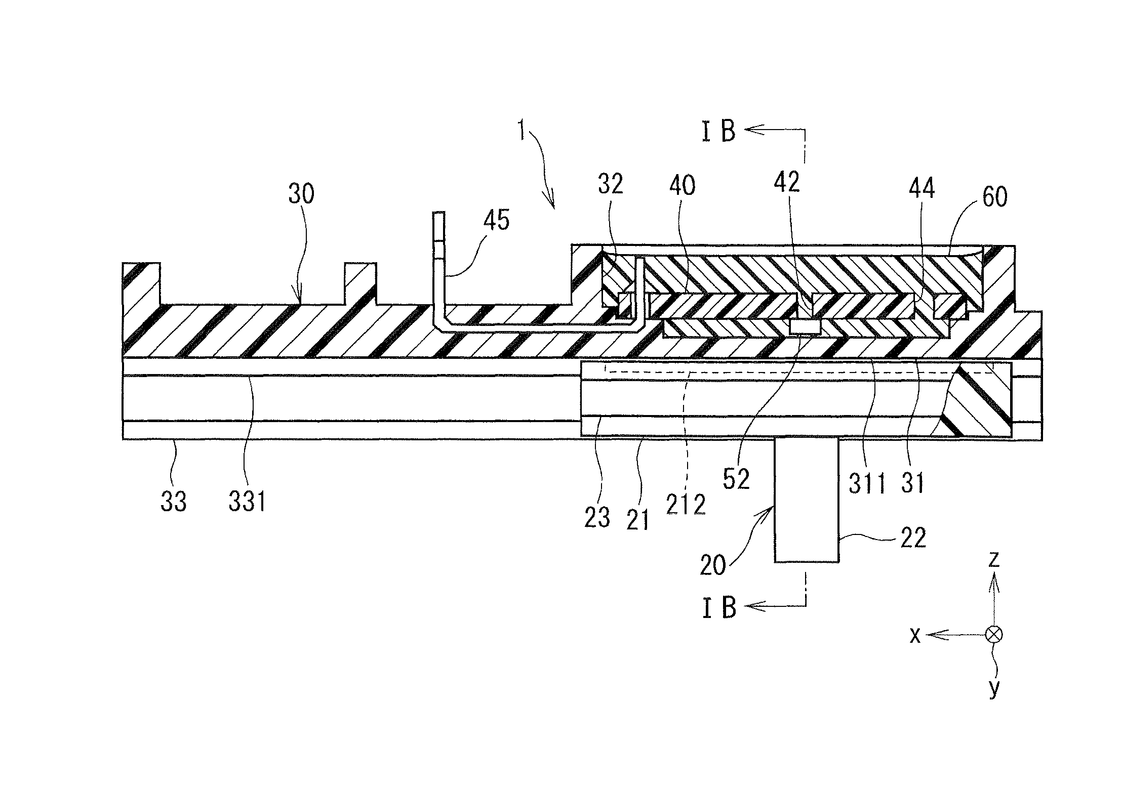
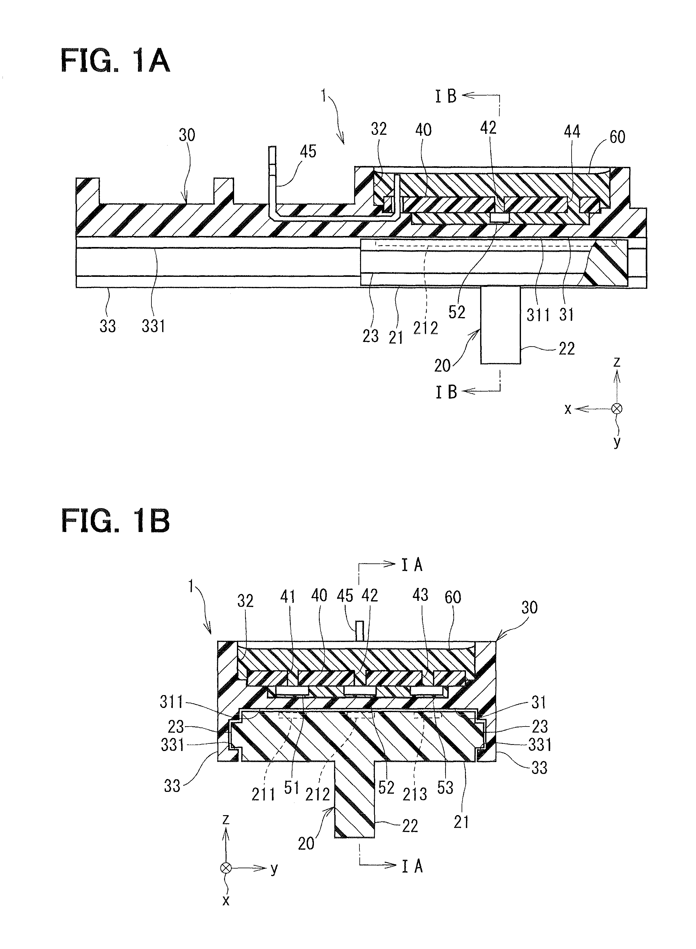
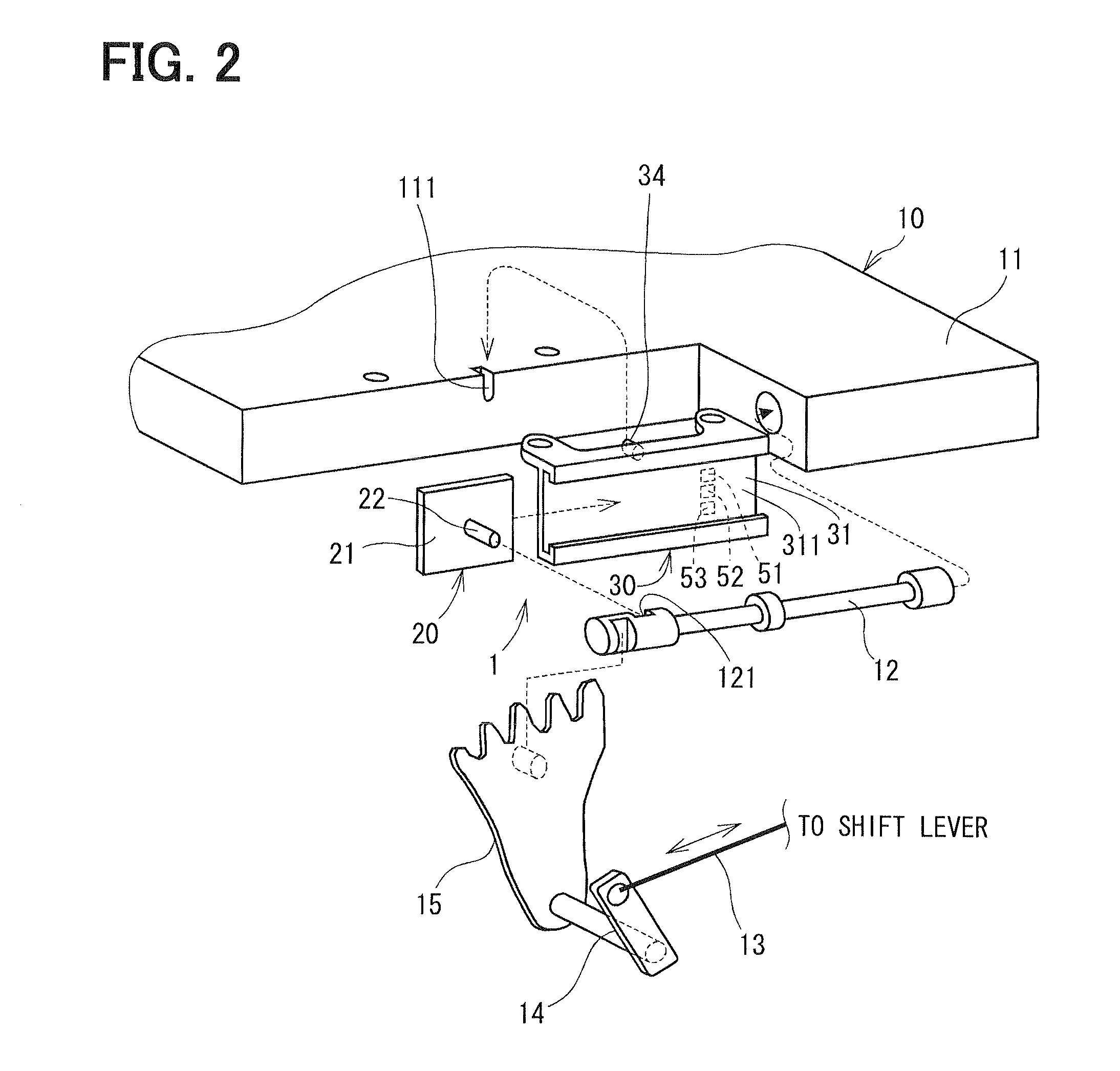
[0023]A range detection device of the first embodiment of the present invention is shown in FIGS. 1A to 2.

[0024]As shown in FIG. 2, a range detection device 1 is attached to a case 11 of a hydraulic control device 10 as a control device. The hydraulic control device 10 has a hydraulic switching valve (hereinafter referred to as manual valve) 12 as a switching portion. When a vehicle occupant selects a shift range (i.e., gear position) and operates a shift lever (not shown), operational force to the shift lever is transmitted to the manual valve 12 of the hydraulic control device 10 via a cable 13, a linkage mechanism 14 and a detent lever 15. The manual valve 12 reciprocates in the case 11 by the operational force so that an oil passage in the hydraulic control device 10 is changed. Accordingly, supply of line-pressure hydraulic oil to multiple friction elements such as a clutch or a brake (not shown) of an automatic transmission is controlled, and the fricti...

second embodiment

[0059](Second Embodiment)

[0060]A part of a range detection device of the second embodiment of the present invention is shown in FIG. 6. In the second embodiment, the shape of the first hole differs from that of the first embodiment.

[0061]FIG. 6 shows a first hole 71 of three first holes formed in the substrate 40, and the magnetic detection element 51 that is installed to the substrate 40 so as to correspond to the position of the first hole 71. As shown in FIG. 6, the first hole 71 is formed such that an opening portion thereof in the first surface of the substrate 40 at a side of the magnetic detection element 51 has a substantially rectangular shape. That is, the first hole 71 is formed to have a slit-like shape (quadrangular prism shape), for example. A width w3 of the opening portion of the first hole 71 in a longitudinal direction is set to be larger than the width w1 of the magnetic detection element 51 in the longitudinal direction. Thus, if the magnetic detection element 51...


PUM


Abstract

In a range detection device, a movable member has a magnetized portion and can move with a manual valve of a control device. A supporting member includes a plate portion having a surface opposed to the magnetized portion and a recess formed in an opposite surface of the plate portion, and supports the movable member such that the movable member is capable of moving parallel with the plate portion. A substrate is placed in the recess and has a first hole that penetrates the substrate. A magnetic detection element is installed to a surface of the substrate at a side of the plate portion to correspond to a position of the first hole, and detects magnetism of the magnetized portion. A sealing member is filled in the recess and covers the substrate and the magnetic detection element.

Description

CROSS REFERENCE TO RELATED APPLICATION[0001]The present application is based on Japanese Patent Application No. 2009-175027 filed on Jul. 28, 2009, the disclosure of which is incorporated herein by reference.FIELD OF THE INVENTION[0002]The present invention relates to a range detection device that detects a shift range of an automatic transmission.BACKGROUND OF THE INVENTION[0003]A range detection device that detects which range is selected in a gear position of an automatic transmission is conventionally known. In such a range detection device, a position of a movable member which moves with a member that switches the gear position of the automatic transmission is detected so that a shift range selected by a vehicle occupant is detected, for example. As a method for detecting the position of the movable member, a contact-type method for detecting the position of the movable member by contacting the movable member with a detection portion, and a noncontact-type method for detecting ...

Claims


Application Information

Patent Timeline
Patent Type & Authority Patents(United States)
IPC IPC(8): G01B7/14
CPCF16H59/105G01D5/2497G01D2205/80
Inventor KITANAKA, TATSUYAKOZAKI, TETSUJIISHINO, HIROTSUGUYOKOYAMA, HAJIME
Owner DENSO CORP
Why Eureka
Try Eureka