Backlight LED Structure, Backlight and Display Device

a backlight led and display device technology, applied in the field of backlight led structure, backlight and display device, can solve the problems of poor phenomenon of bright lines or bright spots at two sides of the display panel, complex assembly, and poor effect of narrow frame design of lcd, and achieve the effect of ensuring the luminous efficacy of the led structur

Active Publication Date: 2014-05-29
BOE TECH GRP CO LTD +1
View PDF3 Cites 1 Cited by
  • Summary
  • Abstract
  • Description
  • Claims
  • Application Information

AI Technical Summary

Benefits of technology

[0008]The prevent invention provides a backlight LED structure, a backlight and a display device for solving the problem of bright spots or bright lines that appear at two sides of display panel due to illumination dark areas exist in the backlight LED structure, meanwhile, it can also guarantee luminous efficacy of the LED structure, does not add new assembly parts, and does not affect the narrow frame design of the LCD.

Problems solved by technology

However, at present, bright spots or bright lines appearing at two sides of the display panel 6 are bad phenomenon frequently occurring in side-edge type LED backlight.
1. The length of the glue frame 4 is increased to shield the bright spots or bright lines at the two sides of the display panel, however, this goes against implementation of narrow frame design of LCD;
2. Reflective sheets are pasted at the two sides of the optical film 3 for shielding, however, this may add assembly parts, and the assembling may be complex.
3. The gap between the LED structure and the light guide plate 2 is increased to achieve light mixing distance, however, this may loss luminous efficacy.

Method used


Image

  • Backlight LED Structure, Backlight and Display Device
  • Backlight LED Structure, Backlight and Display Device
  • Backlight LED Structure, Backlight and Display Device

Examples


Embodiment Construction

[0027]Specific embodiments of the present invention will be described in detail with reference to the figures. The following embodiments are used for explaining the present invention but not for limiting the scope of the present invention.

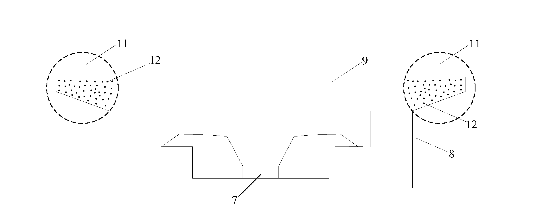
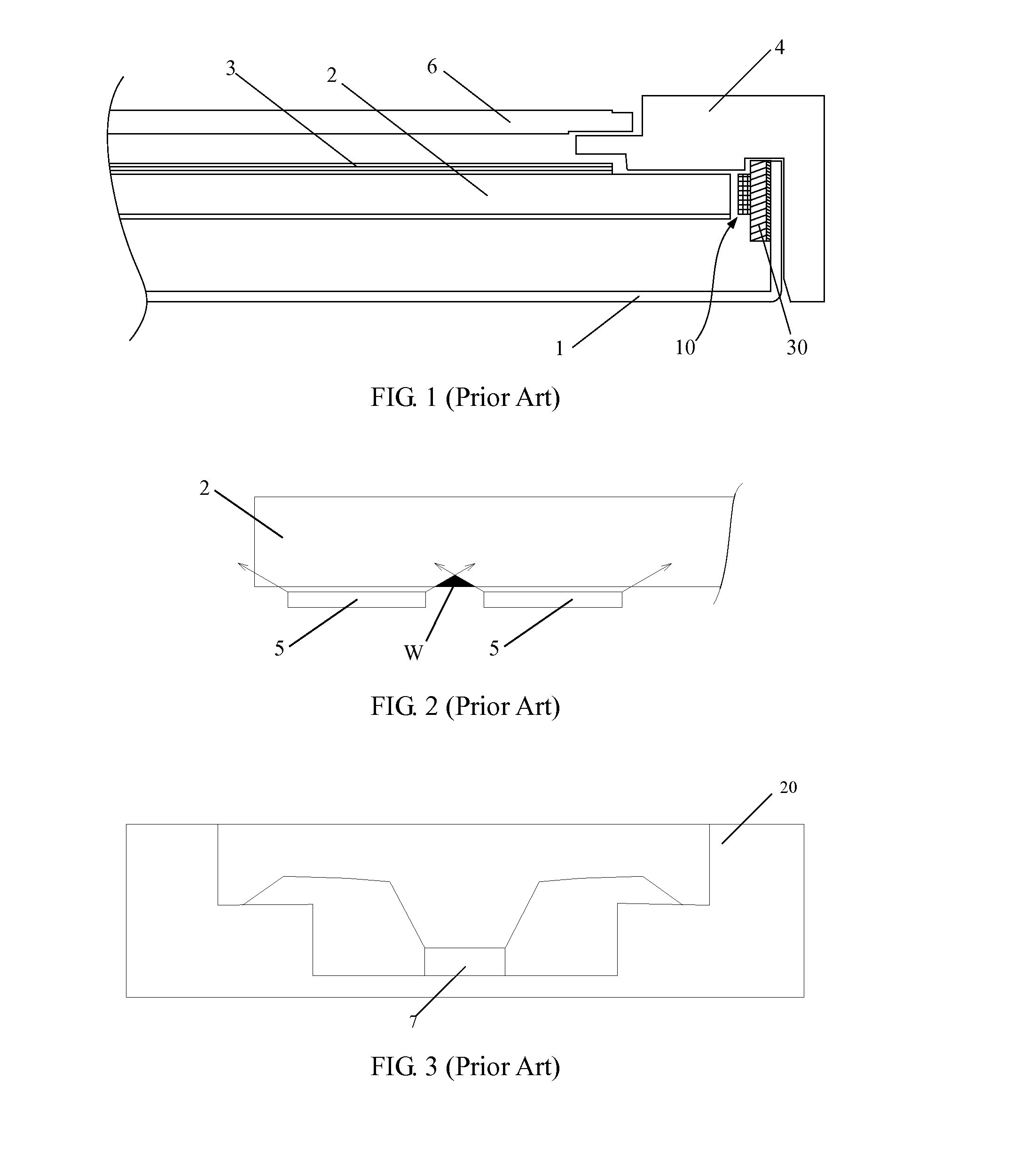
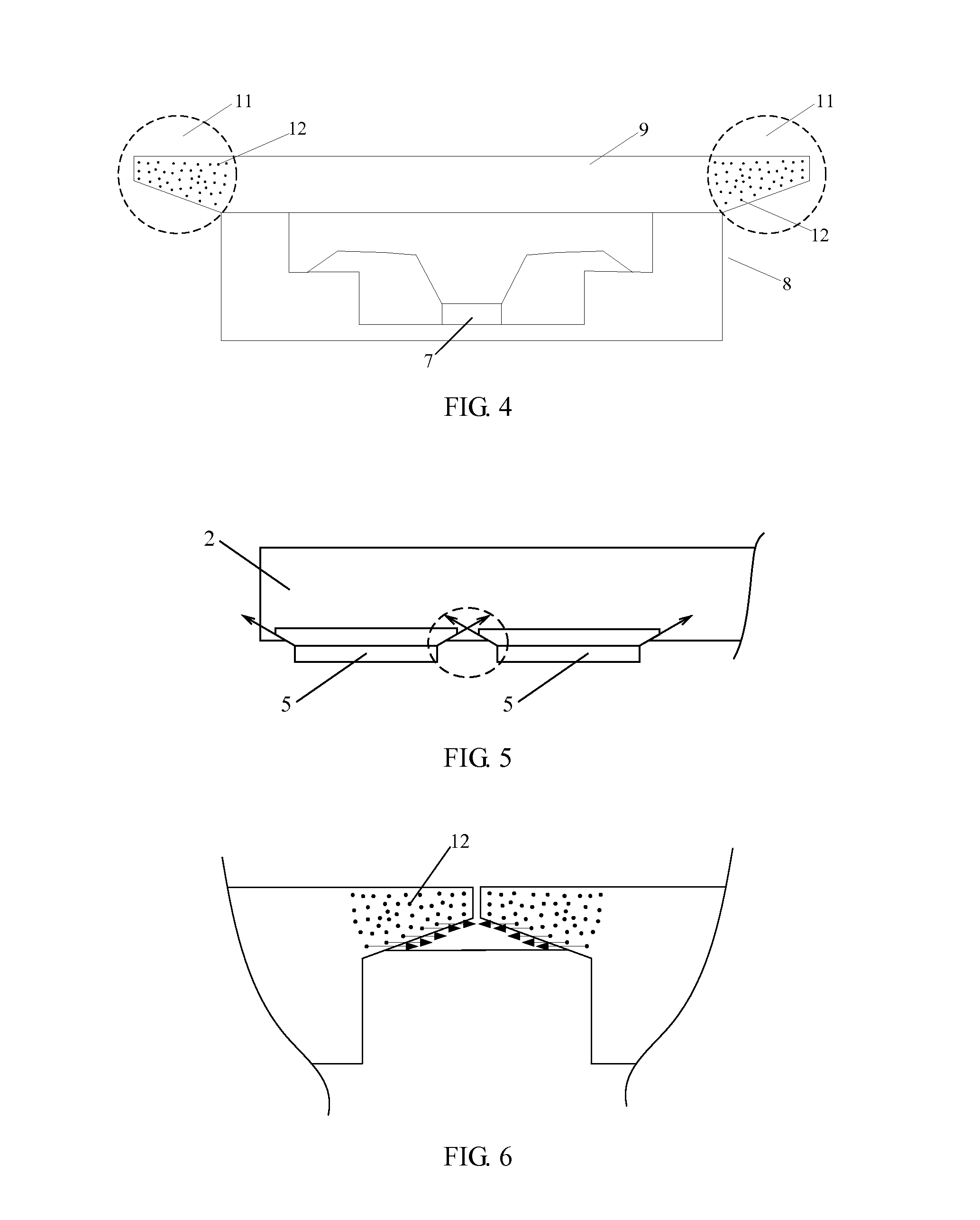
[0028]It should be noted that except for specific designation, the terms for describing the positional relation between the light guide plate and the backlight LED structure in the following description are based on the positional relation as shown in FIG. 1, for example, in FIG. 1, the display panel 6 is above the light guide plate 2 and the backlight LED structure 10, the overall light emitting direction of the backlight LED structure 10 is transversal or horizontal. In addition, the space terms for only describing the backlight LED structure use the positioning direction shown in FIG. 4 as the reference direction, for example, in FIG. 4, the overall light emitting direction of the LED chip 7 is upward, the flange structure 9 is above the LED chi...


PUM


Abstract

The present invention discloses a backlight LED structure, a backlight and a display device. In the backlight LED structure, a flange structure is arranged at the upper side of an LED bracket which is defined when the LED bracket is mounted close to a light guide plate such that the flange structure covers the upper side of the light guide plate when the LED structure and the light guide plate are assembled. In addition, each of the two ends of the flange structure has an angular area extending outwards, and the lower surfaces of the two angular areas are distributed with light guide points. The backlight LED structure can prevent the LED light from being emitted from the fitting gap between the backlight LED structure and the light guide plate, and control direction of light between the backlight LED structures and scatter travel direction of the light.

Description

TECHNICAL FIELD[0001]The present invention relates to a liquid crystal display, and particularly to a backlight LED structure, a backlight and a display device.BACKGROUND ART[0002]Since liquid crystal itself does not emit light, in various liquid crystal display (hereinafter referred to as “LCD”) devices such as liquid crystal display and liquid crystal television, external light sources are required to implement display. The light emitting diode (hereinafter referred to as “LED”) backlight has become the mainstream backlight at present as it has the advantages of good coloring characteristics, long service life, mercury free and environmental protection, and the like.[0003]LED backlight can be divided into two types: a side-edge type LED backlight and a direct type LED backlight according to the distribution position of LED. The side-edge type LED backlight is widely used in LCDs with middle and small sizes due to its advantages of less LEDs required, low cost and thinness. FIG. 1 ...

Claims


Application Information

Patent Timeline
Patent Type & Authority Applications(United States)
IPC IPC(8): F21V8/00
CPCG02B6/0023G02B6/0031G02B6/0068G02B6/0091
Inventor LI, YOUCHEN, XIUYUN
Owner BOE TECH GRP CO LTD
Why Eureka
Try Eureka