
Dynamic Filter Adjustment for Highly-Spectrally-Efficient Communications

a dynamic filter and communication technology, applied in the field of electronic communications, can solve the problems of overly power hungry and/or spectrally inefficient communication methods and systems, and achieve the effect of reducing the number of incoming and outgoing signals, and improving the efficiency of communication

Active Publication Date: 2014-05-29
AVAGO TECH INT SALES PTE LTD
View PDF4 Cites 31 Cited by
  • Summary
  • Abstract
  • Description
  • Claims
  • Application Information

AI Technical Summary

Benefits of technology

This patent suggests a way to adjust filters in a way that improves communication over a range of frequencies. This can increase efficiency in communication and reduce errors.

Problems solved by technology

Existing communications methods and systems are overly power hungry and / or spectrally inefficient.

Method used


Image

  • Dynamic Filter Adjustment for Highly-Spectrally-Efficient Communications
  • Dynamic Filter Adjustment for Highly-Spectrally-Efficient Communications
  • Dynamic Filter Adjustment for Highly-Spectrally-Efficient Communications

Examples


Embodiment Construction

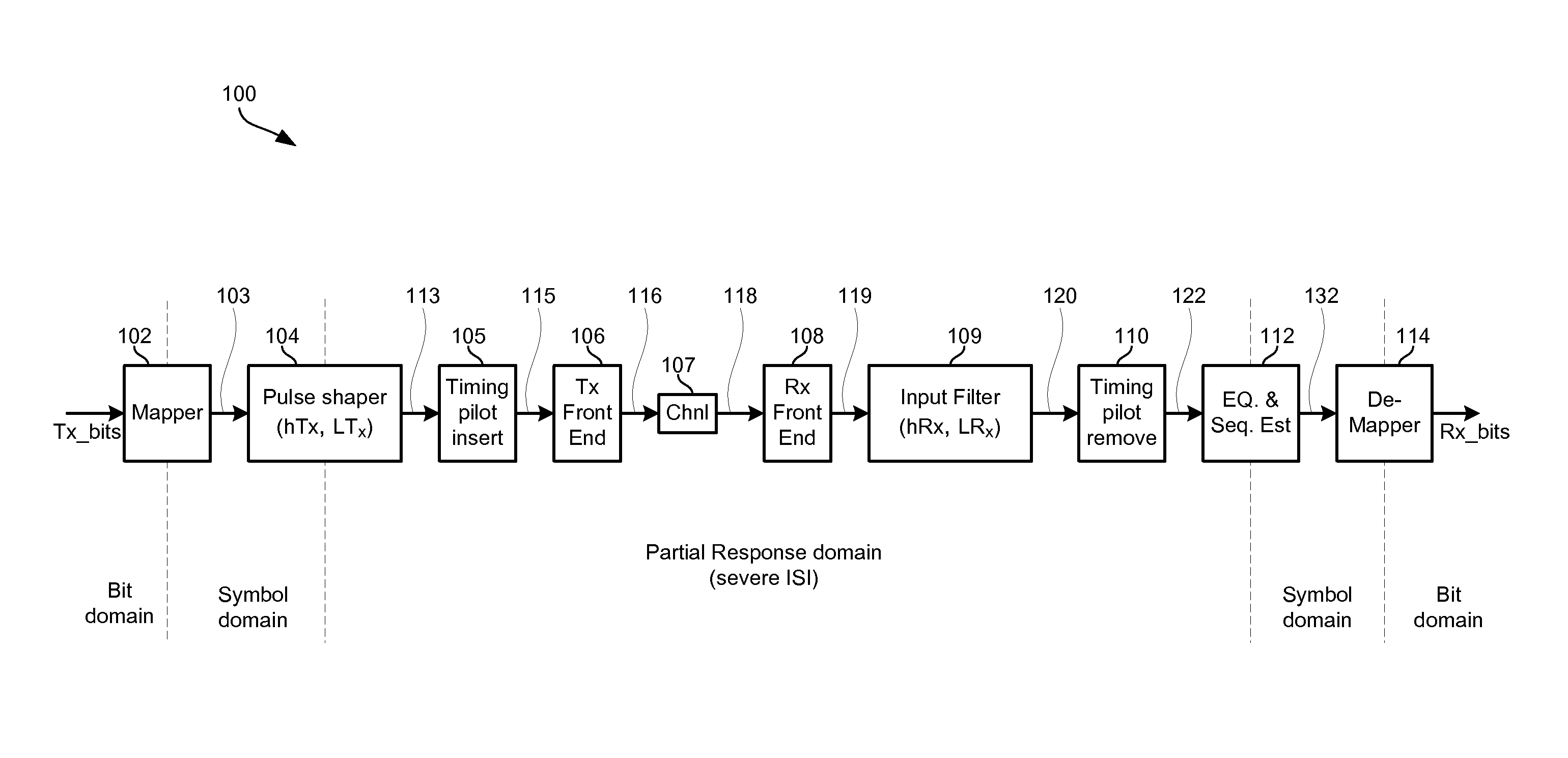
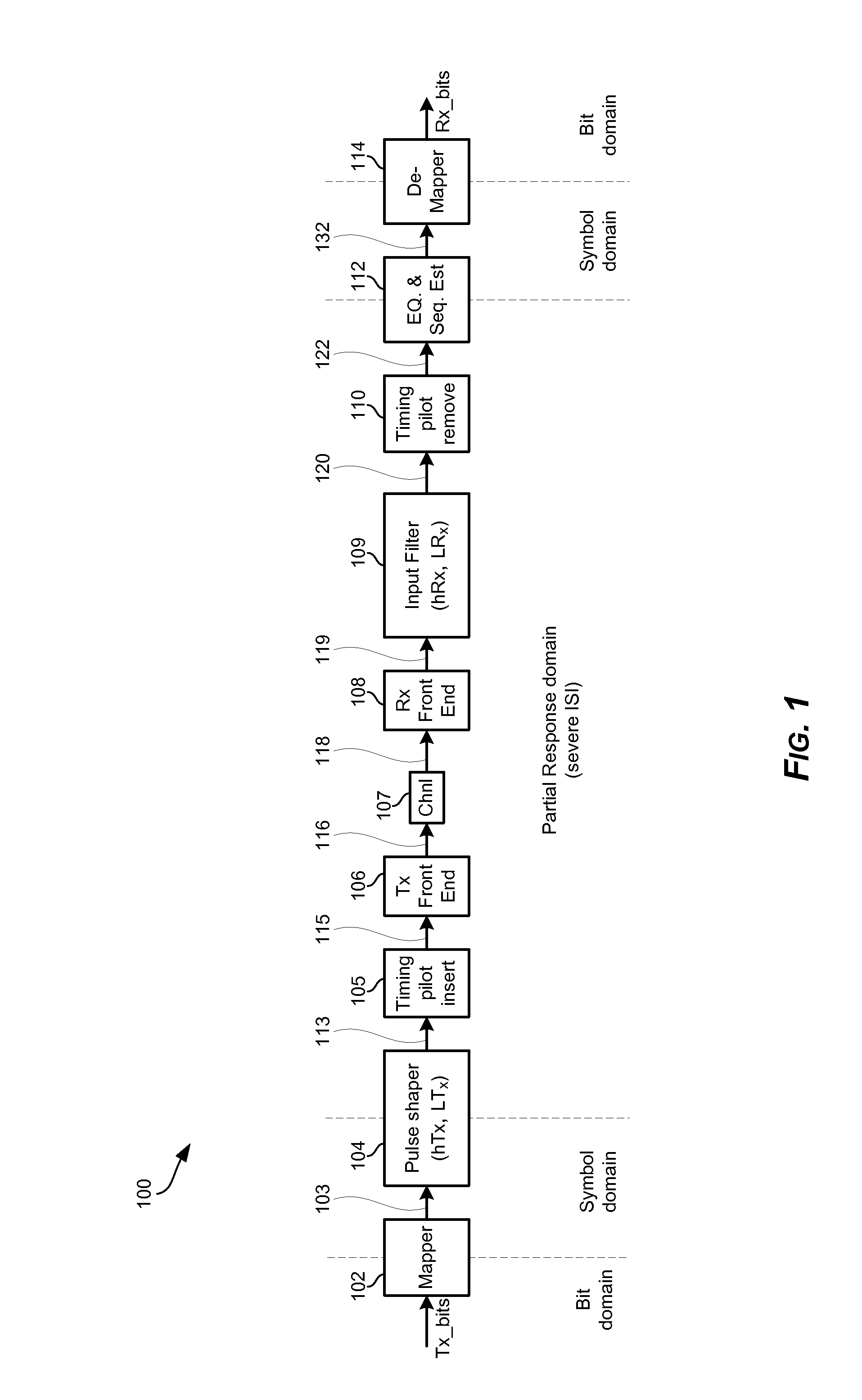
[0028]The present disclosure relates to a method and system for design and optimization of partial response pulse shape filter.

[0029]As utilized herein the terms “circuits” and “circuitry” refer to physical electronic components (i.e. hardware) and any software and / or firmware (“code”) which may configure the hardware, be executed by the hardware, and or otherwise be associated with the hardware. As used herein, for example, a particular processor and memory may comprise a first “circuit” when executing a first plurality of lines of code and may comprise a second “circuit” when executing a second plurality of lines of code. As utilized herein, “and / or” means any one or more of the items in the list joined by “and / or”. As an example, “x and / or y” means any element of the three-element set {(x), (y), (x, y)}. As another example, “x, y, and / or z” means any element of the seven-element set {(x), (y), (z), (x, y), (x, z), (y, z), (x, y, z)}. As utilized herein, the terms “block” and “mod...


PUM


Abstract

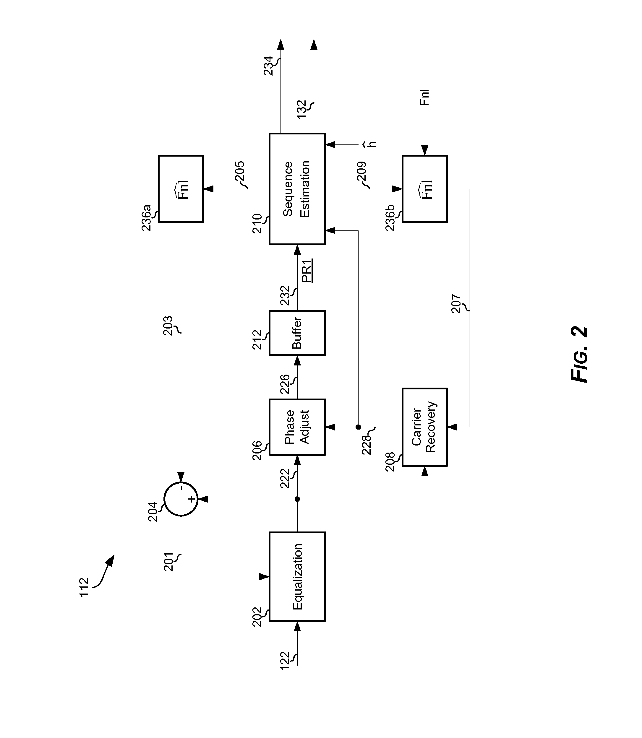
A method and system for dynamic configuring of one or both of a transmitter pulse-shaping filter and a receiver pulse-shaping filter to generate a total partial response that incorporates a predetermined amount of inter-symbol interference (ISI). The predetermined amount of ISI is determined based on an estimation process during extraction of data from an output of the receiver pulse-shaping filter, such that performance of total partial-response-based communication matches or surpasses performance of communication incorporating filtering based on no or near-zero ISI. The reconfiguring may comprise obtaining data relating to changes affecting one or more of: the pulse-shaping filtering, and a channel and / or an interface used in the communication of data based on the total partial response, and adjusting the filter configuration, such as by determining a new optimized filtering configuration or changes to existing configurations (e.g., by applying a filtering optimization process).

Description

CLAIM OF PRIORITY[0001]This patent application is a continuation of U.S. patent application Ser. No. 13 / 755,008 filed on Jan. 31, 2013 (now patented as U.S. Pat. No. 8,571,131), which in turn, claims priority to U.S. Provisional Patent Application Ser. No. 61 / 662,085 entitled “Apparatus and Method for Efficient Utilization of Bandwidth” and filed on Jun. 20, 2012, now expired. This patent application is also a non-provisional of U.S. Provisional Patent Application Ser. No. 61 / 726,099 entitled “Modulation Scheme Based on Partial Response” and filed on Nov. 14, 2012, U.S. Provisional Patent Application Ser. No. 61 / 729,774 entitled “Modulation Scheme Based on Partial Response” and filed on Nov. 26, 2012; and U.S. Provisional Patent Application Ser. No. 61 / 747,132 entitled “Modulation Scheme Based on Partial Response” and filed on Dec. 28, 2012.[0002]Each of the above identified applications is hereby incorporated herein by reference in its entirety.INCORPORATION BY REFERENCE[0003]This ...

Claims


Application Information

Patent Timeline
Patent Type & Authority Applications(United States)
IPC IPC(8): H04B1/04
CPCH04B1/0475H04L1/0054H04L1/0057H04L1/0071H04L1/206H04L25/03197H04L25/03834H04L25/03949H04B1/16H04L27/3405H04L25/0328H04L27/38
Inventor ELIAZ, AMIR
Owner AVAGO TECH INT SALES PTE LTD
Learn More