A Dose Counter

a technology of dose counter and dose, applied in the field of dose counter, can solve the problems of difficult to provide simplistic dose counters or dose counting assemblies

Inactive Publication Date: 2014-06-05
CIPLA LTD
View PDF2 Cites 5 Cited by
  • Summary
  • Abstract
  • Description
  • Claims
  • Application Information

AI Technical Summary

Benefits of technology

[0035]The invention therefore provides a simple mechanical counter mechanism that is actuated each time a dose is delivered from the MDI canister to keep track of the doses dispensed by, or remaining in, the inhaler device.

Problems solved by technology

In particular, and as evident from the prior knowledge and art, there are difficulties in providing simplistic dose counters or dose counting assemblies that reliably “count” the release of medicament doses from the medicament containers / inhalers, specifically, MDIs.

Method used


Image

  • A Dose Counter
  • A Dose Counter
  • A Dose Counter

Examples


first embodiment

[0049]the invention is shown in FIGS. 1 to 5 of the accompanying drawings.

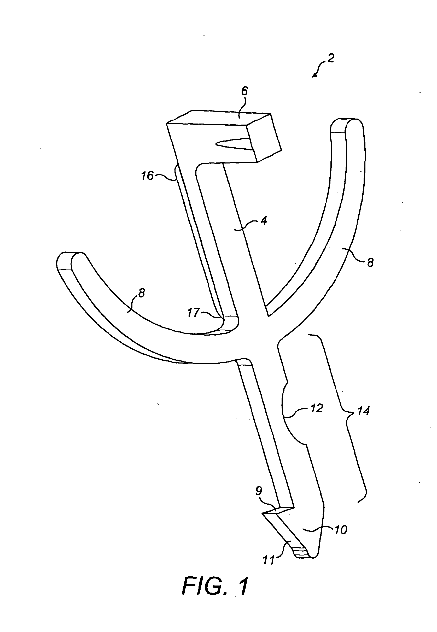
[0050]FIG. 1 shows the actuator component 2 in isolation. The actuator 2 is a unitary component comprising a central beam 4 with a generally rectangular cross-section. A protrusion 6 for engagement with an MDI canister (not shown) extends from a front face of the beam 4, at a first end thereof. Extending from opposite sides of the central beam 4, at around its mid point, are a pair of curved arms 8 which initially extend away from the central beam 4 at right angles before curving in the direction of the protrusion 6.

[0051]A hook or catch 10 is provided at a second end of the beam 4 for engagement with the teeth of a drive wheel (see FIG. 2). The hook 10 is provided as a generally triangular protrusion extending from one side of the central beam 4 to provide a first face 9 to engage with the teeth of said drive wheel, and a second angled face 11 arranged at a shallow angle to the central beam 4.

[0052]A cut-out ...

second embodiment

[0079]the invention is shown in FIGS. 6 and 7.

[0080]An actuator 102, drive wheel 118 and driven wheel 126 are provided as in the first embodiment, and are similar in a number of respects. The following description will, therefore, focus on the key differences found in the components of the second embodiment.

[0081]FIG. 6 shows a view of the second embodiment that is similar to the view of the first embodiment provided in FIG. 4.

[0082]The actuator 102 is essentially identical to the actuator 2 of FIG. 1. However, a further raised area 146 is provided on the front face of the central beam 4.

[0083]The drive wheel 118 differs from the drive wheel 18 of the first embodiment in two ways. Firstly, the boss 122 has a greater diameter than the boss 22 in the first embodiment such that the drive tooth 124 protrudes beyond the outer diameter of the saw-shaped teeth 120. Secondly, a pair of ratchet teeth 142 are provided on a inner circumferential surface of the drive wheel 118. The ratchet teet...

third embodiment

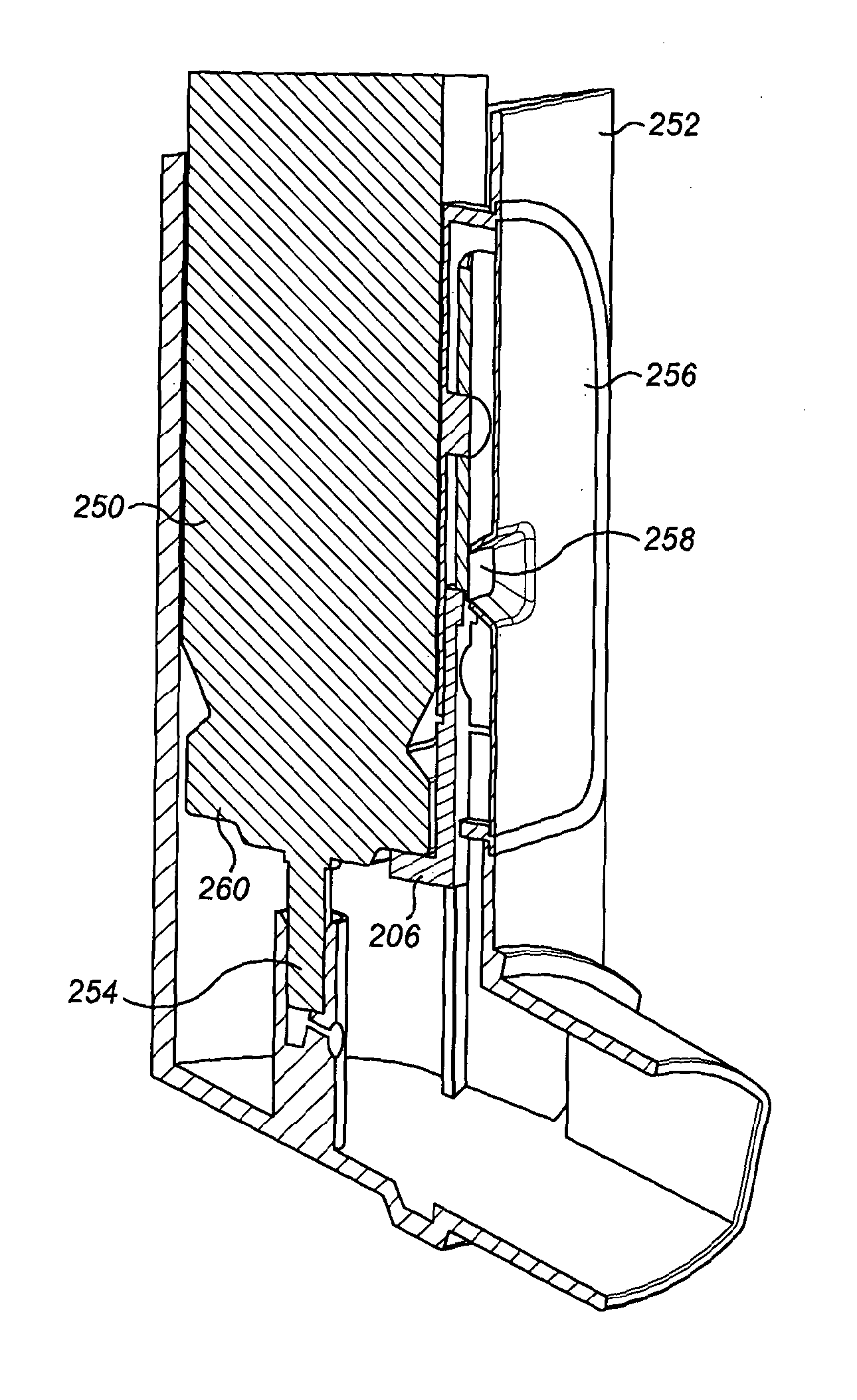
[0088]the invention is shown in FIGS. 8 and 9. Once again the dose counter mechanism comprises an actuator 202 and driven wheel 226 and the interaction and operation of the components 202,218,226.

[0089]The most apparent difference visible in FIG. 8 is that the driven wheel 226 of the third embodiment is provided as a flat disc rather than as a ring as in the first and second embodiments. This means that, whereas in the first and second embodiments the drive wheel 18,118 was positioned radially inside the driven wheel / ring 26,126, the drive wheel 218 of the second embodiment is positioned radially outside the driven wheel 226.

[0090]Around the majority of the driven wheel 226 are provided inlets 233, similar to those provided by the wall-like protrusion 32,132 on the driven ring 26,126 of the first and second embodiments. The inlets 233 are provided in the third embodiment by selective thinner parts of the driven wheel 226 around its periphery.

[0091]The boss 222 of the drive wheel 218...


PUM


Abstract

The present invention relates to a dose counter. Particularly, but not exclusively, the invention relates to a dose counter for use with a Metered Dose Inhaler (MDI). The dose counter comprises a rotary counting element (26) and an actuator (2). The actuator (2) is movable relative to the rotary counting element (26) and comprises a shaped part (17) which can move into and out of engagement with a complementary feature (33) of the rotary counting element (26) when the actuator (2) moves between first and second positions. When the shaped part (17) of the actuator (2) is engaged with the complementary feature (33) of the rotary counter element (26), rotation of the rotary counter element (26) is resisted.

Description

CROSS-REFERENCE TO RELATED APPLICATIONS[0001]This application is a filing under 35 U.S.C. 371 of International Application No. PCT / GB2011 / 001724 filed Dec. 15, 2011, entitled “A Dose Counter,” which claims priority to Indian Patent Application Nos. 1384 / MUM / 2011 filed May 4, 2011 and 3424 / MUM / 2011 filed on Dec. 5, 2011, which applications are incorporated by reference herein in their entirety.FIELD OF INVENTION[0002]The present invention relates to a dose counter, and particularly, but not exclusively to a dose counter for use with a Metered Dose Inhaler (MDI)BACKGROUND & PRIOR ART[0003]Medicament inhaler devices are well known. They come in many different forms and may be used in the treatment of a number of ailments.[0004]Inhalers are typically used by patients over prolonged periods without supervision. In particular for conditions like asthma, it is important for a user to have a reliable record of the level of medicament remaining in an inhaler so as to ensure that they have a ...

Claims


Application Information

Patent Timeline
Patent Type & Authority Applications(United States)
IPC IPC(8): A61M15/00
CPCA61M15/009A61M15/0065A61M15/0075A61M2205/276G06M1/04G06M1/042A61M15/00
Inventor MALHOTRA, GEENARAO, XERXESPURANDARE, SHRINIVAS MADHUKAR
Owner CIPLA LTD
Why Eureka
Try Eureka