
Drag knob and fishing reel using the same

Active Publication Date: 2014-06-05
SHIMANO INC
View PDF15 Cites 6 Cited by
  • Summary
  • Abstract
  • Description
  • Claims
  • Application Information

AI Technical Summary

Benefits of technology

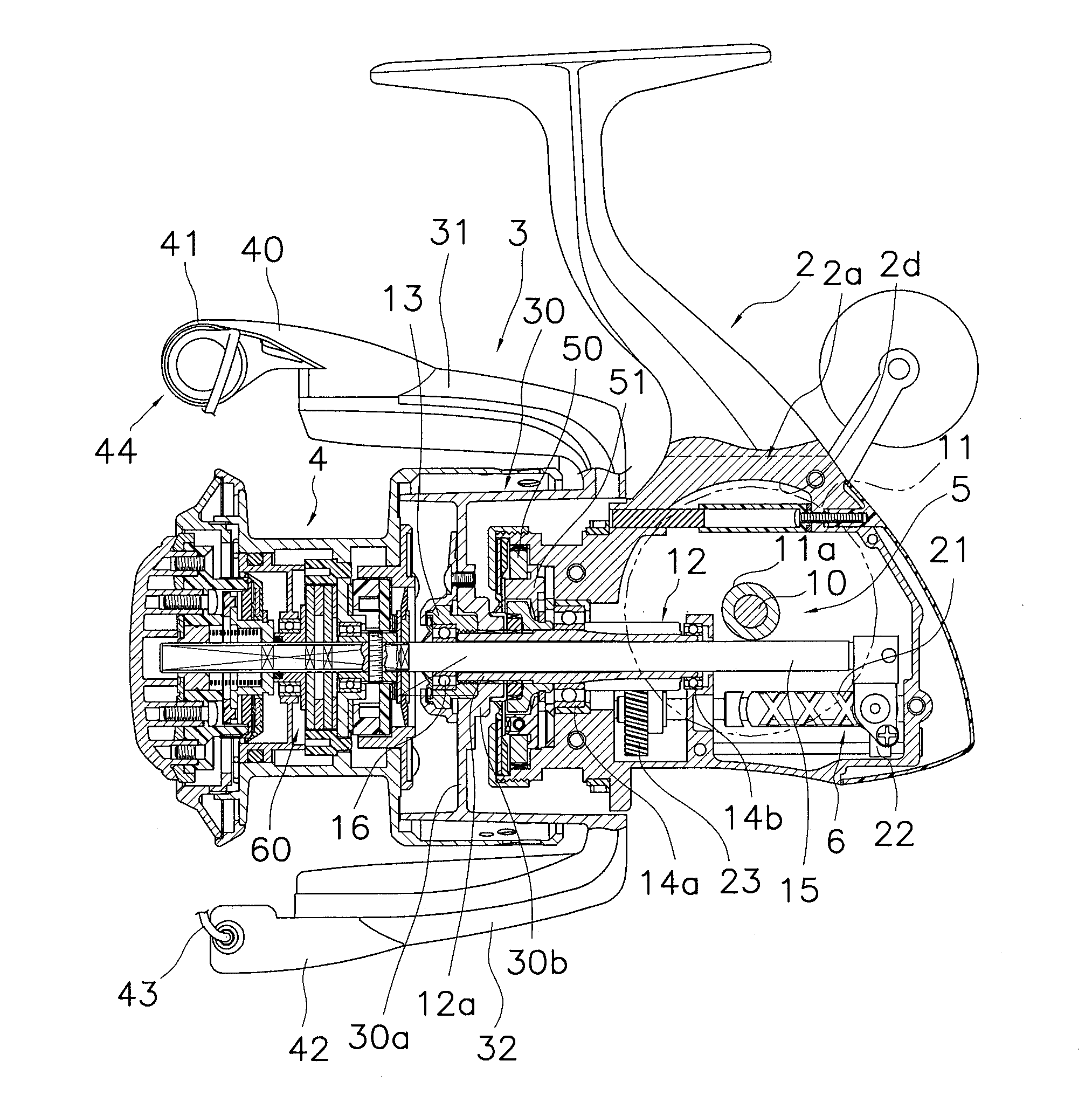
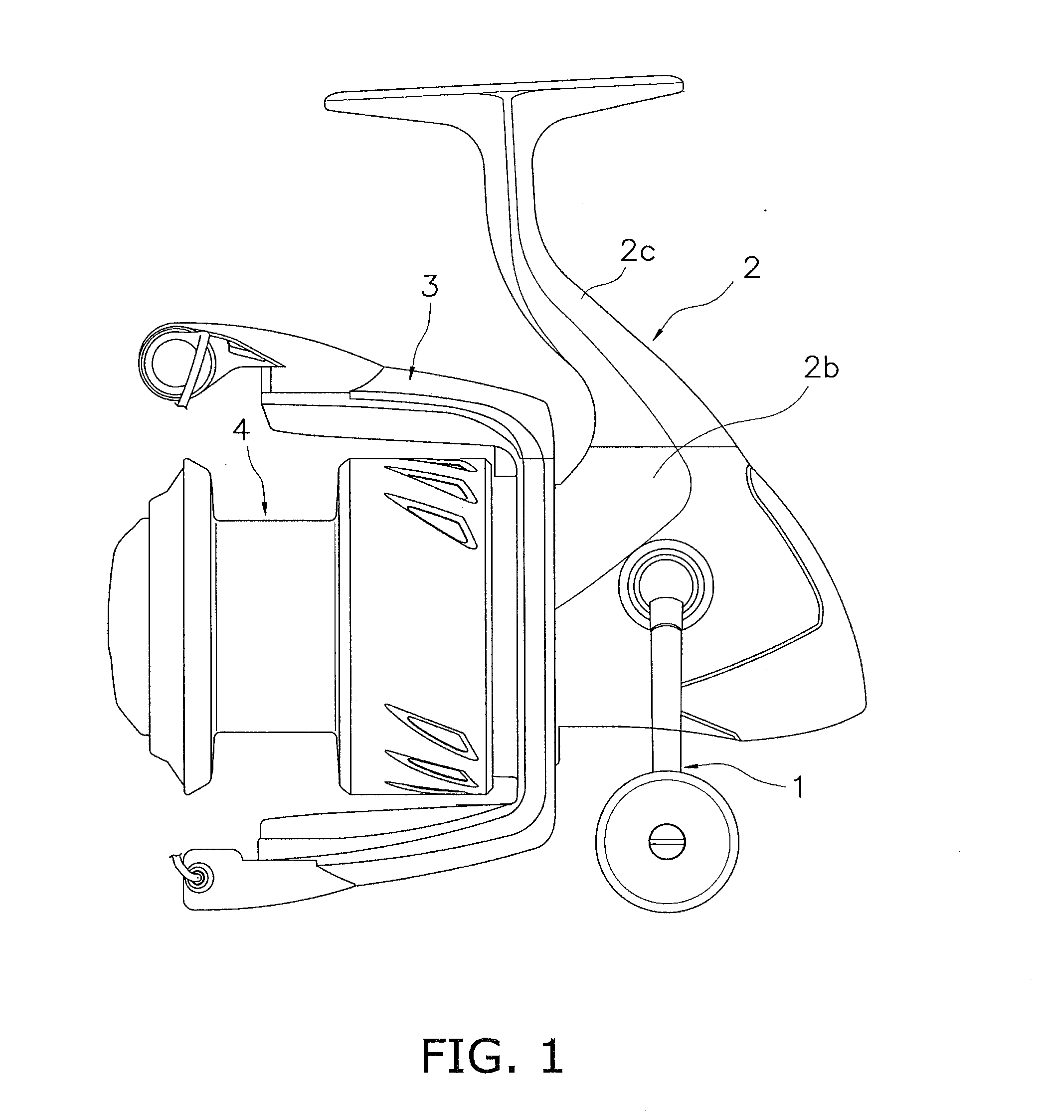
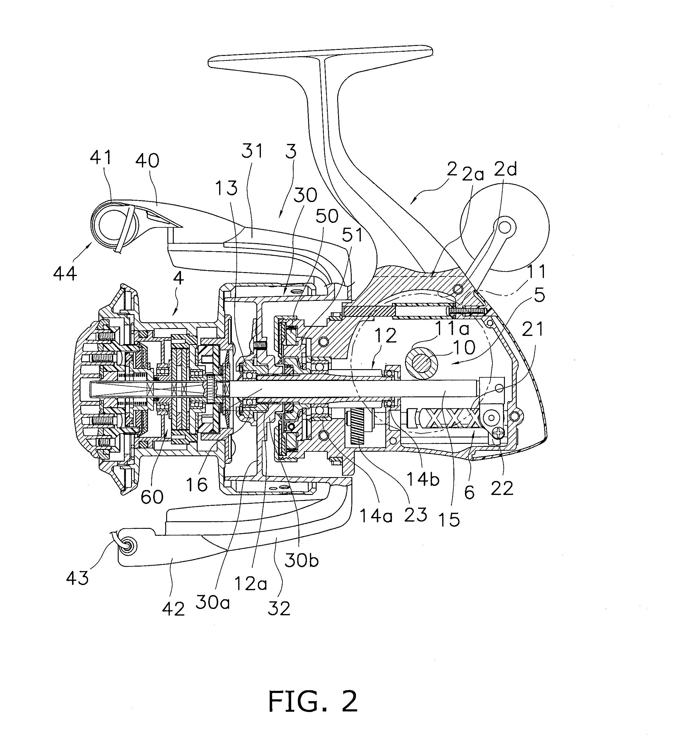
The present invention is about preventing the deformation of a coil spring in a drag knob and fishing reel. The patent describes a drag knob that includes a coil spring, a receiver member, and a slide member. The coil spring extends and contracts in response to the rotation of the operating member, and the receiver member is responsible for applying drag force to the spool. The slide member is positioned between the coil spring and the receiver member, and it has a lower friction coefficient than the receiver member. The technical effect of this design is to prevent the coil spring from getting deformed when the drag knob is used repeatedly.

Problems solved by technology

In other words, chances are that such various springs are twisted and deformed when receiving force in its circumferential direction.

Method used


Image

  • Drag knob and fishing reel using the same
  • Drag knob and fishing reel using the same
  • Drag knob and fishing reel using the same

Examples


modification 1

[0071]For example, in the aforementioned exemplary embodiment, the slide member 63 is disposed between the coil spring 73 and the receiver member 66. However, as illustrated in FIG. 9, the slide member 63 can be disposed between the coil spring 73 and the operating member 67. Alternatively, the slide members 63 can be disposed both between the coil spring 73 and the receiver member 66 and between the coil spring 73 and the operating member 67.

[0072]The drag knob 61 according to the present modification 1 is the one for regulating the drag force of the drag mechanism 60 configured to brake the rotation of the spool 4 rotatably attached to the reel unit 2 for the fishing reel. The drag knob 61 includes the operating member 67, the coil spring 73, the receiver member 66, and the slide member 63. The operating member 67 is rotatably mounted to the reel unit 2. The coil spring 73 extends and contracts in the rotary axis direction of the operating member 67 in conjunction with the rotatio...

modification 2

[0074]The coil spring 73 can be such a coiled wave spring as illustrated in FIG. 10. When explained in detail, the coil spring 73 can be produced by forming a wire rod in a convexo-concave shape in the axial direction and then by winding the convexo-concave portions consecutively in a wavy shape in a spiral direction. The coil spring 73 has a structure that the convex / concave portions of axially adjacent wound portions of the wire rod are opposed to each other and the opposed convex portions make contact with each other at the apices thereof. Thus, with use of such a coiled wave spring as the coil spring 73, urging force equivalent to that of a normal coil spring can be maintained, while the axial length thereof can be reduced than that of the normal coil spring.

modification 3

[0075]The coil spring 73 can have a circular cross-section in the axial direction. In other words, such a coil spring can be used that is produced by forming a wire rod with a circular cross-section in a spiral shape. Even with such structure, similarly to the aforementioned exemplary embodiment, the friction force acting on the coil spring 73 can be reduced, while the torsional deformation of the coil spring 73 can be prevented.


PUM


Abstract

A drag knob for regulating drag force of a drag mechanism configured to brake rotation of a spool rotatably mounted to a reel unit of a fishing reel includes an operating member, a coil spring, a receiver member, and a slide member. The operating member is rotatably mounted to the reel unit. The coil spring extends and contracts in a rotary axis direction of the operating member in conjunction with rotation of the operating member. The receiver member is configured to receive urging force of the coil spring and apply drag force to the spool. The slide member is disposed between the coil spring and the receiver member in the rotary axis direction. The slide member has a friction coefficient less than a friction coefficient of the receiver member.

Description

CROSS-REFERENCE TO RELATED APPLICATIONS[0001]This application claims priority to Japanese Patent Application No. 2012-265031 filed on Dec. 4, 2012. The entire disclosure of Japanese Patent Application No. 2012-265031is hereby incorporated by reference in its entirety.BACKGROUND[0002]1. Field of the Invention[0003]The present invention relates to a drag knob for regulating the drag force of a drag mechanism and a fishing reel using the same.[0004]2. Background Art[0005]In general, a fishing reel includes a drag mechanism for braking spool rotation. The drag mechanism is mainly formed by a drag knob and a friction part. The drag knob serves to regulate drag force. The friction part is formed by a plurality of drag washers. Further, the drag knob includes an operating member, a receiver member, and a coil spring. The receiver member is attached to the operating member while being rotatable relatively thereto. The coil spring is disposed between the operating member and the receiver mem...

Claims


Application Information

Patent Timeline
IPC IPC(8): A01K89/02
CPCA01K89/027A01K89/015F16F1/06A01K89/02
Inventor HIRAOKA, HIROKAZU
Owner SHIMANO INC
Features
  • Generate Ideas
  • Intellectual Property
  • Life Sciences
  • Materials
  • Tech Scout
  • Unparalleled Data Quality
  • Higher Quality Content
  • 60% Fewer Hallucinations
Learn More