Touchscreen

a technology of touch screen and cross-capacitance, applied in the field of touch screen, can solve the problems of inability to secure high detection sensitivity, erroneous detection, and inability to achieve high detection sensitivity, and achieve the effect of improving visibility and changing cross-capacitan

Active Publication Date: 2014-06-05
MITSUBISHI ELECTRIC CORP
View PDF1 Cites 23 Cited by
  • Summary
  • Abstract
  • Description
  • Claims
  • Application Information

AI Technical Summary

Benefits of technology

[0011]An object of the present invention is to provide a touchscreen with small cross-capacitance between the row-directional lines and the column-directional lines, in which a great change in cross-capacitance occurs when the touchscreen is touched by a pointer, with improved visibility.
[0013]With the touchscreen described above, by providing the floating electrode, an interval can be provided between the row-directional line and the column-directional line by the width of the floating electrode. Hence, by providing the floating electrode, cross-capacitance between the row-directional line and the column-directional line can be reduced. Further, it becomes possible to increase the amount of change in cross-capacitance when the touchscreen is touched. Hence, as compared to the case where the floating electrode is not provided, touch detection sensitivity can be increased.

Problems solved by technology

The projected capacitive touch panel described above involves the following problem: when the electric field coupling between the first electrode and the second electrode is great, a change in cross-capacitance do not easily occur when the touch panel is touched by a pointer such as a finger, making it impossible to secure high detection sensitivity.
Setting low detection sensitivity, erroneous detection tends to occur.

Method used


Image

  • Touchscreen
  • Touchscreen
  • Touchscreen

Examples


first preferred embodiment

[0044]

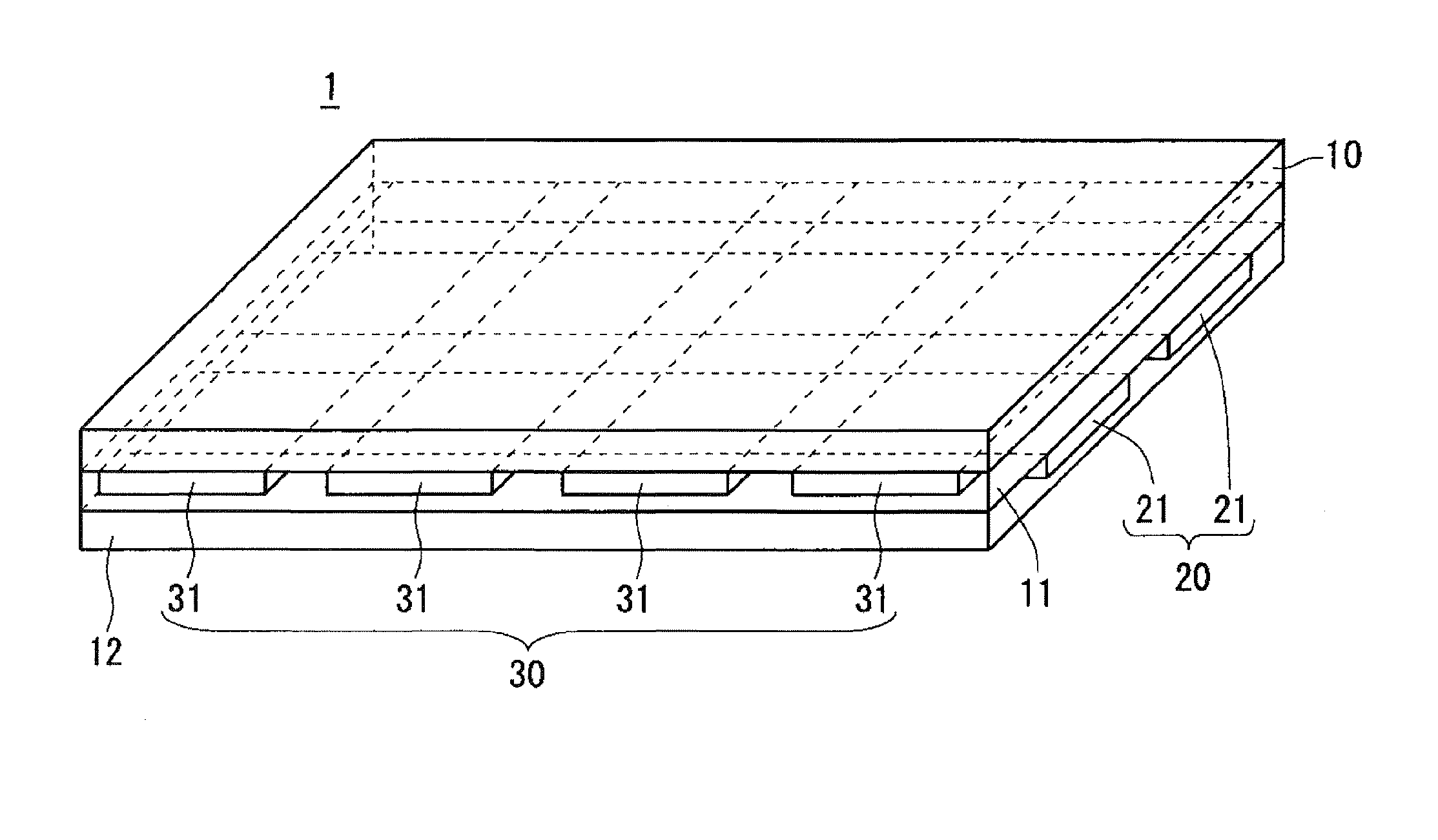
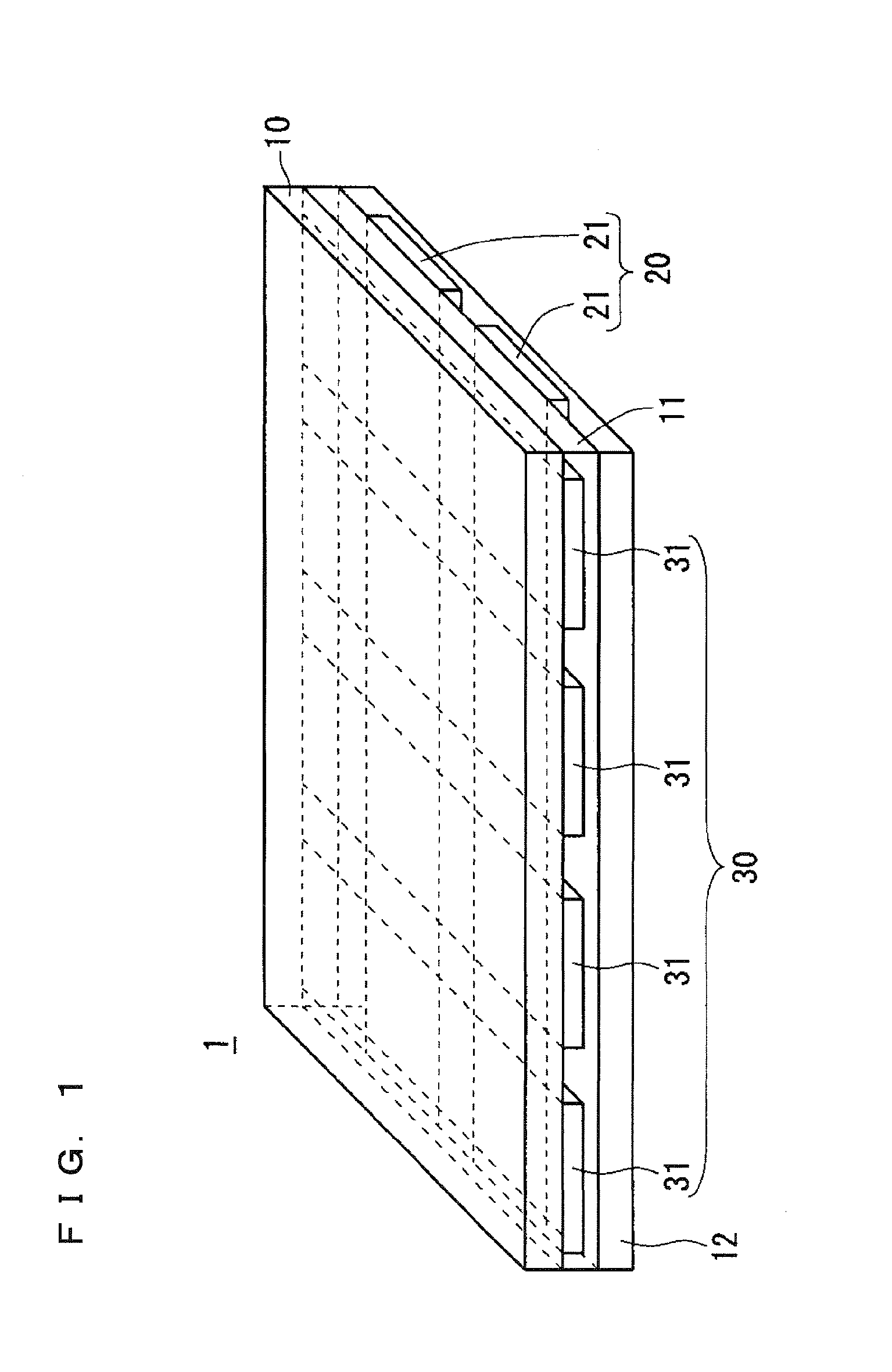
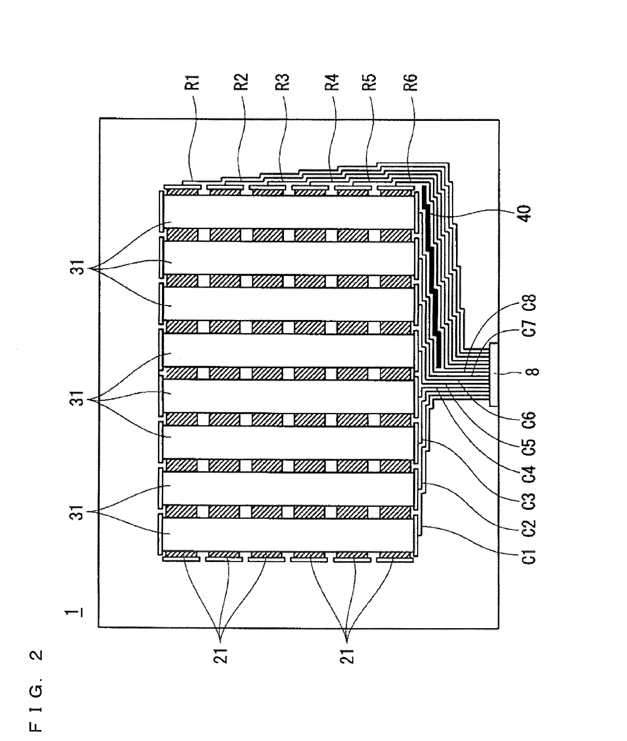
[0045]Firstly, with reference to FIGS. 1 and 2, a description will be given of the layer structure of a touchscreen 1 according to the present preferred embodiment. The touchscreen 1 according to the present preferred embodiment is the projected capacitive touchscreen.

[0046]FIG. 1 is a perspective view of the layer structure of the touchscreen 1 according to the present preferred embodiment. The upper surface layer of the touchscreen 1 is a transparent substrate 10 made of a transparent glass material or transparent resin. On the back surface of the transparent substrate 10, an upper electrode 30 is formed.

[0047]Further, on the back surface of the transparent substrate 10, an interlayer insulating film 11 is formed to cover the upper electrode 30. The interlayer insulating film 11 is a transparent insulating film such as a silicon nitride film and a silicon oxide film. On the back surface of the interlayer insulating film 11, a lower electrode 20 is formed.

[0048]Further, on th...

second preferred embodiment

[0099]

[0100]In the first preferred embodiment, in the region where the row-directional lines 21 or the column-directional lines 31 are formed, except for the region where these lines overlap each other in a planar view, one of the row-directional lines 21 and the column-directional lines 31 are arranged.

[0101]Accordingly, since the row-directional lines 21 and the column-directional lines 31 are arranged at layers differing in depth, the lines tend to be visually recognized because of difference in reflectivity between the row-directional lines 21 and the column-directional lines 31.

[0102]In the present preferred embodiment, row-directional dummy lines 33 are further arranged at the upper electrode 30 at the layer above the row-directional lines 21. Further, column-directional dummy lines 22 are further arranged at the lower electrode 20 at the layer below the column-directional lines 31.

[0103]Further, in the touchscreen according to the present preferred embodiment, the mesh of the...

third preferred embodiment

[0126]

[0127]The structure of the lower electrode 20 and the upper electrode 30 of the touchscreen according to the present preferred embodiment is different from the second preferred embodiment (FIG. 15) in that the unit pattern of lines is arc-shaped.

[0128]FIG. 16 shows the unit pattern which is common to the row-directional line 21, the column-directional line 31, the row-directional dummy line 33, and the column-directional dummy line 22 according to the present preferred embodiment.

[0129]The unit pattern of lines in the present preferred embodiment is formed by S-shaped lines crossing each other and a circular line about the intersection of the S-shaped lines. The radius of an arc forming each S-shaped line is r, and the radius of the circular line is R.

[0130]Note that interval P1 in the row direction and interval P2 in the columnar direction of the unit pattern are each 200 μm. Further, radius r of the arc is 100 μm and radius R of the circular line is 80 μm.

[0131]FIG. 17 is a ...


PUM

PropertyMeasurementUnit
widthaaaaaaaaaa
thicknessaaaaaaaaaa
thicknessaaaaaaaaaa

Abstract

A touchscreen of the present invention is covered by wiring patterns of a row-directional line and a column-directional line being upper and lower two layers. A step height that is produced by an upper electrode riding on a lower electrode when a floating electrode is provided at a region adjacent to the row-directional line and the column-directional line is suppressed.

Description

BACKGROUND OF THE INVENTION[0001]1. Field of the Invention[0002]The present invention relates to a touchscreen.[0003]2. Description of the Background Art[0004]A touch panel is an apparatus that detects a touch with a finger or the like and specifies the positional coordinates of the touched position. The touch panel is receiving attention as one of excellent user interface means. The touch panels of various types, such as the resistive type and the capacitive type, are commercially available.[0005]Generally, a touch panel is structured by a touchscreen in which a touch sensor is built, and a detecting apparatus that specifies the positional coordinates of a touch based on a signal from the touchscreen.[0006]The capacitive touch panels include a projected capacitive touch panel (for example, see Japanese Patent Application Laid-Open No. 2012-103761).[0007]The projected capacitive touch panel is capable of detecting a touch even when the front side of the touchscreen in which the touc...

Claims


Application Information

Patent Timeline
Patent Type & Authority Applications(United States)
IPC IPC(8): G02F1/1333
CPCG06F3/0412G06F3/0445G06F3/0446G06F2203/04112
Inventor NAKAMURA, TATSUYAIMAMURA, TAKUJIONO, TAKESHINAKAGAWA, NAOKIAGARI, MASAFUMIMORI, SEIICHIROMIYAYAMA, TAKASHI
Owner MITSUBISHI ELECTRIC CORP
Why Eureka
Try Eureka