Touchscreen
a technology of touch screen and cross-capacitance, applied in the field of touch screen, can solve the problems of inability to secure high detection sensitivity, erroneous detection, and inability to achieve high detection sensitivity, and achieve the effect of improving visibility and changing cross-capacitan
- Summary
- Abstract
- Description
- Claims
- Application Information
AI Technical Summary
Benefits of technology
Problems solved by technology
Method used
Image
Examples
first preferred embodiment
[0045]
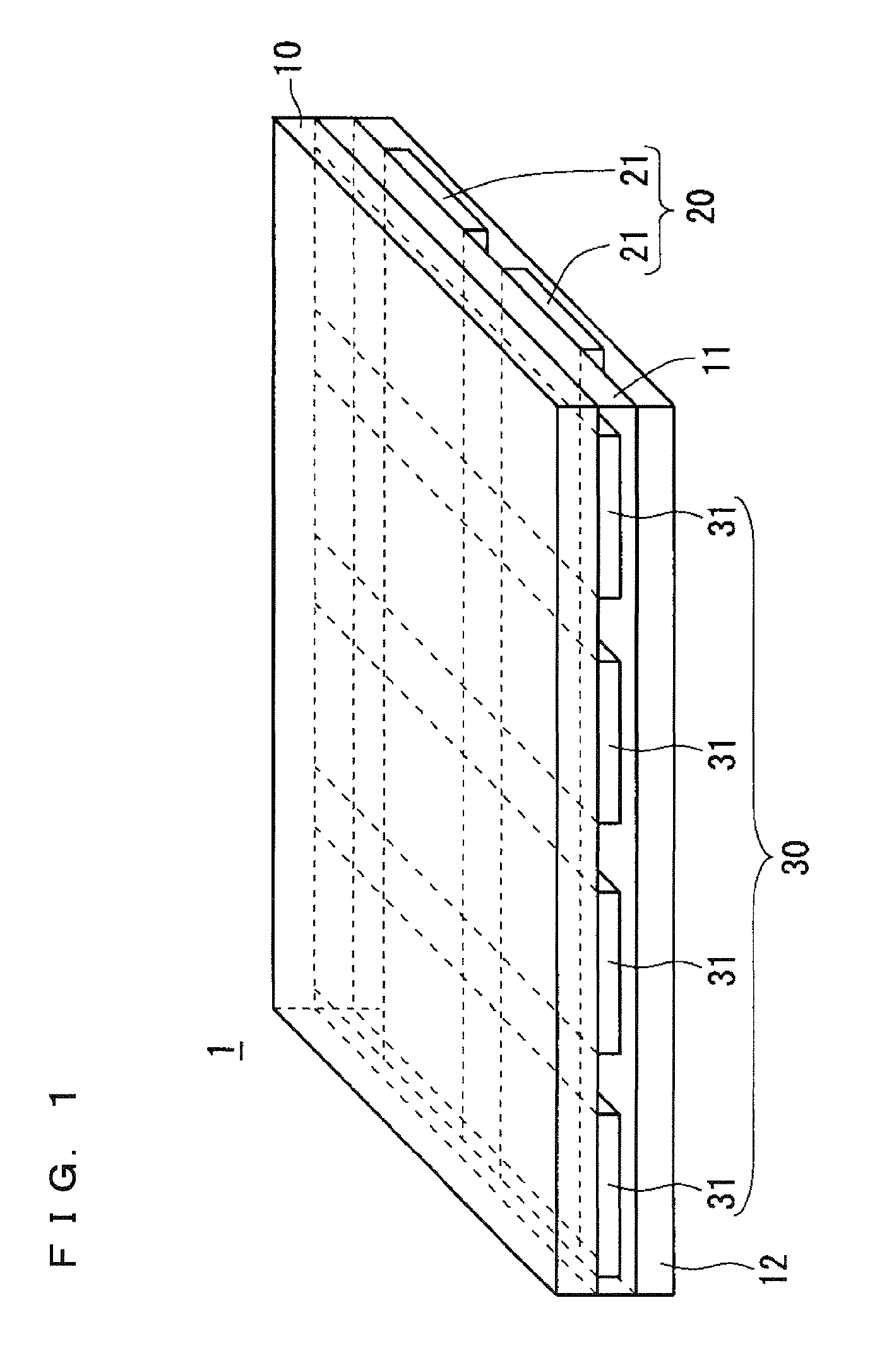
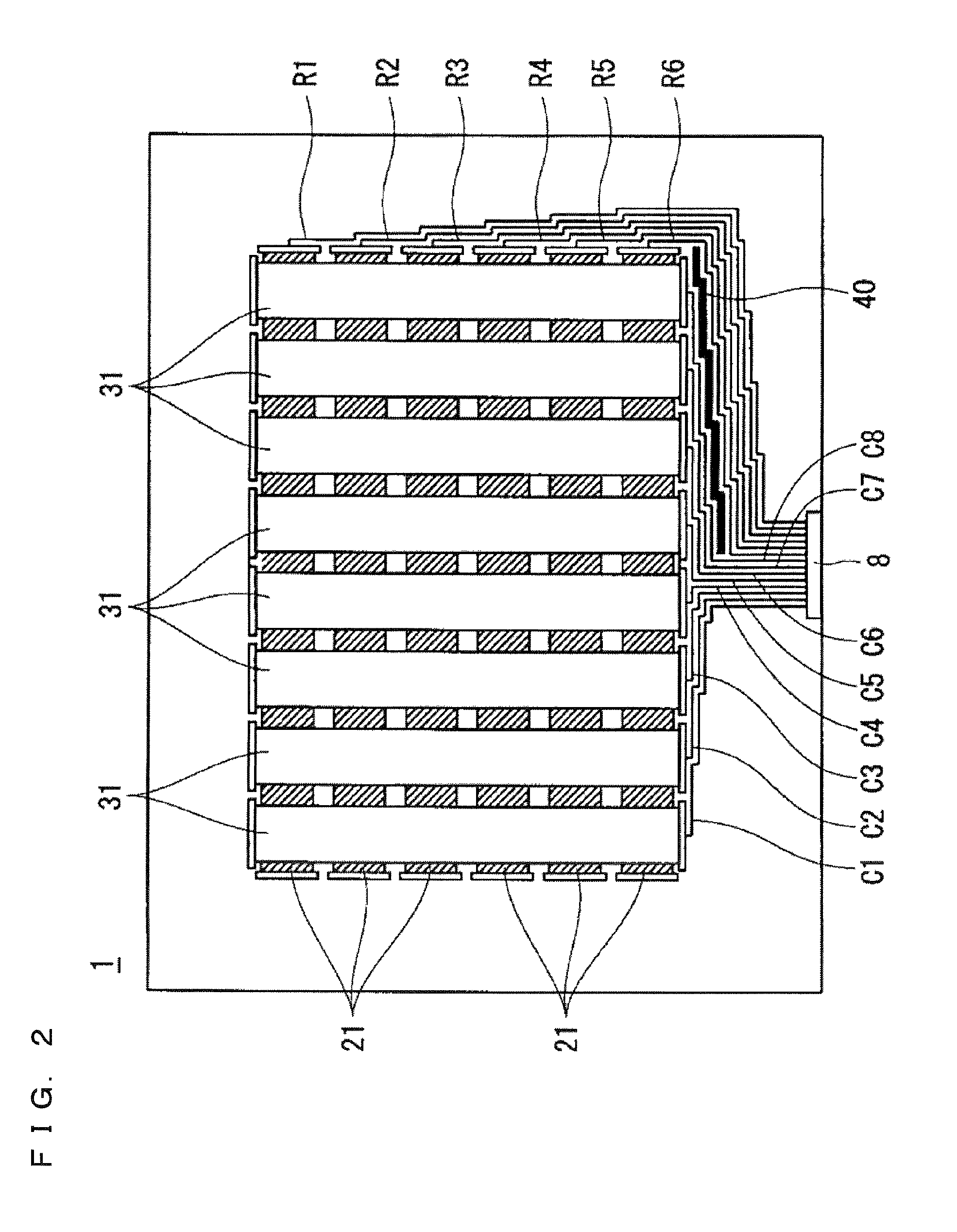
[0046]Firstly, with reference to FIGS. 1 and 2, a description will be given of the layer structure of a touchscreen 1 according to the present preferred embodiment. The touchscreen 1 according to the present preferred embodiment is the projected capacitive touchscreen.
[0047]FIG. 1 is a perspective view of the layer structure of the touchscreen 1 according to the present preferred embodiment. The upper surface layer of the touchscreen 1 is a transparent substrate 10 made of a transparent glass material or transparent resin. On the back surface of the transparent substrate 10, an upper electrode 30 is formed.
[0048]Further, on the back surface of the transparent substrate 10, an interlayer insulating film 11 is formed to cover the upper electrode 30. The interlayer insulating film 11 is a transparent insulating film such as a silicon nitride film and a silicon oxide film. On the back surface of the interlayer insulating film 11, a lower electrode 20 is formed.
[0049]Further, on th...
second preferred embodiment
[0100]
[0101]In the first preferred embodiment, in the region where the row-directional lines 21 or the column-directional lines 31 are formed, except for the region where these lines overlap each other in a planar view, one of the row-directional lines 21 and the column-directional lines 31 are arranged.
[0102]Accordingly, since the row-directional lines 21 and the column-directional lines 31 are arranged at layers differing in depth, the lines tend to be visually recognized because of difference in reflectivity between the row-directional lines 21 and the column-directional lines 31.
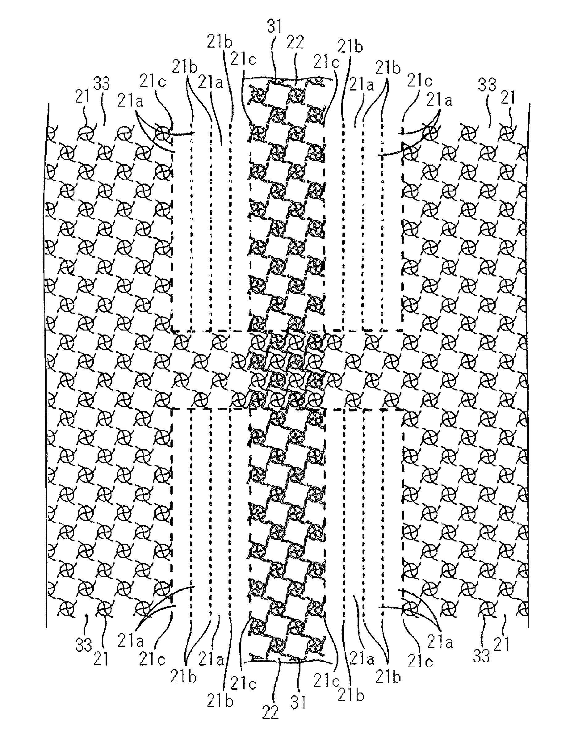
[0103]In the present preferred embodiment, row-directional dummy lines 33 are further arranged at the upper electrode 30 at the layer above the row-directional lines 21. Further, column-directional dummy lines 22 are further arranged at the lower electrode 20 at the layer below the column-directional lines 31.
[0104]Further, in the touchscreen according to the present preferred embodiment, the mesh of the...
third preferred embodiment
[0127]
[0128]The structure of the lower electrode 20 and the upper electrode 30 of the touchscreen according to the present preferred embodiment is different from the second preferred embodiment (FIG. 15) in that the unit pattern of lines is arc-shaped.
[0129]FIG. 16 shows the unit pattern which is common to the row-directional line 21, the column-directional line 31, the row-directional dummy line 33, and the column-directional dummy line 22 according to the present preferred embodiment.
[0130]The unit pattern of lines in the present preferred embodiment is formed by S-shaped lines crossing each other and a circular line about the intersection of the S-shaped lines. The radius of an arc forming each S-shaped line is r, and the radius of the circular line is R.
[0131]Note that interval P1 in the row direction and interval P2 in the columnar direction of the unit pattern are each 200 μm. Further, radius r of the arc is 100 μm and radius R of the circular line is 80 μm.
[0132]FIG. 17 is a ...
PUM
 Abstract
Description
Claims
Application Information
 - R&D
- Intellectual Property
- Life Sciences
- Materials
- Tech Scout
- Unparalleled Data Quality
- Higher Quality Content
- 60% Fewer Hallucinations
Browse by: Latest US Patents, China's latest patents, Technical Efficacy Thesaurus, Application Domain, Technology Topic, Popular Technical Reports.
© 2025 PatSnap. All rights reserved.Legal|Privacy policy|Modern Slavery Act Transparency Statement|Sitemap|About US| Contact US: help@patsnap.com


