Image forming apparatus and cartridge
- Summary
- Abstract
- Description
- Claims
- Application Information
AI Technical Summary
Benefits of technology
Problems solved by technology
Method used
Image


Examples
first embodiment
[0018]An image forming apparatus according to First Embodiment of the present invention will be described. Incidentally, in this embodiment, as the image forming apparatus, a laser beam printer to which a process cartridge is detachably mountable is exemplified.
(General Structure of Image Forming Apparatus)
[0019]FIG. 1 is a schematic view showing a cross section of a general structure of an image forming apparatus 100. As shown in FIG. 1, the image forming apparatus 100 includes a feeding portion 10, an image forming portion 20 and a discharging portion 30.
[0020]The image forming portion 20 includes a cartridge 1 which is detachably mountable to an apparatus main assembly 100A of the image forming apparatus 100 and which performs a part of an image forming process, a transfer roller 21 for transferring an image onto a recording material P, a laser exposure device 22 for irradiating a photosensitive member with laser light, a fixing device 23 for heat-fixing the recording material P,...
second embodiment
[0060]Second Embodiment of the image forming apparatus according to the present invention will be described. In this embodiment, an operation after the detection of the incompletely mounted state is different from the operation in First Embodiment. Incidentally, constituent portions (elements) identical or similar to those in First Embodiment are represented by the same reference numerals or symbols and will be omitted from redundant description.
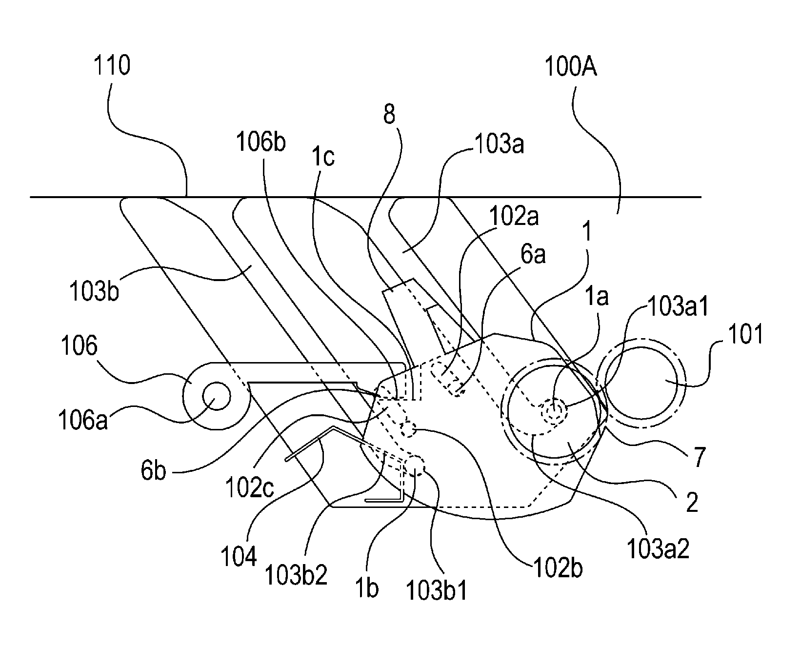
[0061]Parts (a) and (b) of FIG. 5 are schematic views, for illustrating an operation of the apparatus main assembly 100A when the incompletely mounted state of the cartridge 1 is detected, showing a positioning portion of the cartridge 1 and the neighborhood thereof when the image forming apparatus 100 is viewed from a longitudinal direction of the cartridge 1 in this embodiment.
[0062]In each of these figures, a cross section is a plane which is perpendicular to the longitudinal direction of the cartridge 1 and which passes through a central...
third embodiment
[0068]Third Embodiment of the image forming apparatus according to the present invention will be described. In this embodiment, constitutions of the cartridge guide, the electrical contacts and the detecting system are different from those in First Embodiment. Incidentally, constituent portions (elements) identical or similar to those in First Embodiment are represented by the same reference numerals or symbols and will be omitted from redundant description.
(Mounting of Cartridge)
[0069]Parts (a) to (d) of FIG. 6 are schematic views showing a positioning portion of the cartridge 1 and the neighborhood thereof when the image forming apparatus 100 in this embodiment is in viewed from a longitudinal direction of the cartridge 1. A cross section in each of the figures is a plane which is perpendicular to the longitudinal direction of the cartridge 1 and which passes through a central portion of the apparatus main assembly 100A.
[0070]Part (a) of FIG. 6 shows an unmounted state immediately...
PUM
 Abstract
Description
Claims
Application Information