Hand Dryer

a hand dryer and dryer technology, applied in the field of hand dryers, can solve the problems of ineffective heating of the air in this way, high power input, and inability to immediately provide heat, and achieve the effect of optimal drying results

Inactive Publication Date: 2014-06-12
ELECTROSTAR
View PDF15 Cites 0 Cited by
  • Summary
  • Abstract
  • Description
  • Claims
  • Application Information

AI Technical Summary

Benefits of technology

[0034]In order to achieve optimal drying results, it is advantageous when the exit surface area of the exit openings is designed such that the exit flow speed of the air is greater than approximately 35 m per second.
[0035]In order to prevent that during the drying process the water droplets reach the user, it is advantageous when the air stream that is exiting from the exit openings blows slightly at a slant away from the user of the hand dryer and the heat rays are oriented slightly at a slant away from the user of the hand dryer.

Problems solved by technology

Heating of the air in this way is not very effective and requires high power input.
Moreover, after turning on the blower motor, the heat is not immediately available because time is required in order for the heating coil to reach its required temperature.
In addition, a non-uniform heat distribution may result which means a loss of comfort for the user.

Method used


Image

  • Hand Dryer
  • Hand Dryer

Examples


Embodiment Construction

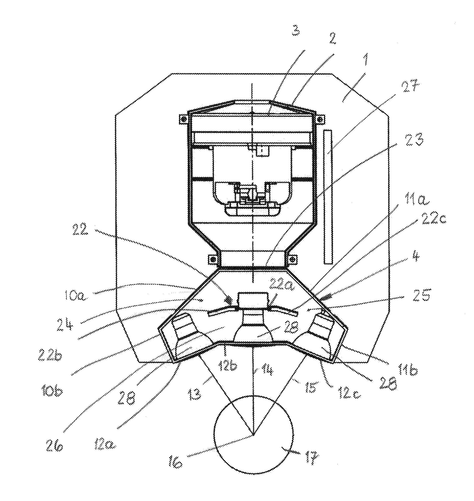
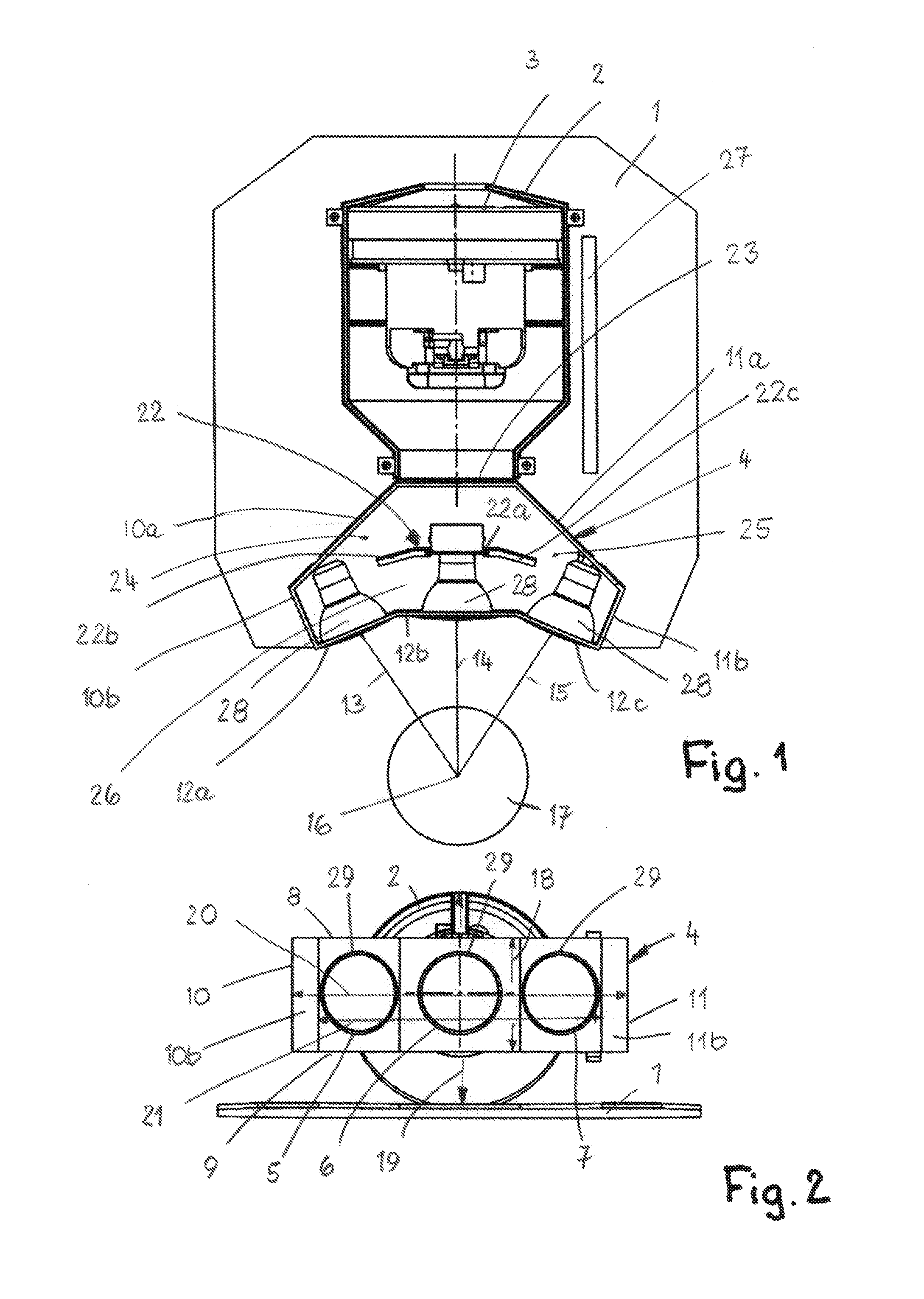
[0040]The hand dryer is attached to a mounting plate 1, for example, that is fastened to a wall or the like, for example, by a screw connection. The hand dryer has a housing 2 with an interior in which a blower motor 3 is arranged with which, as is known in the art, an air stream is generated that exits at the bottom from the housing 2.

[0041]An air guide 4 is connected to the bottom end of the housing 2 and has a rectangular cross-section (FIG. 2); it is provided with three exit openings 5 to 7. They each have a circular cross-section and advantageously are of the same size.

[0042]The air guide 4 widens initially continuously away from the housing in the flow direction of the air. The air guide 4 has parallel longitudinal sidewalls 8, 9 that are connected to each other by narrow sidewalls 10, 11. The sidewalls each are comprised of two wall sections 10a, 10b; 11a, 11b that are positioned at an obtuse angle relative to each other. The wall sections 10a, 11a adjoin the exit end 23 of t...


PUM


Abstract

A hand dryer has a housing having an interior. At least one exit opening communicating with the interior of the housing is provided. At least one blower motor is arranged in the interior of the housing and blows air in an air stream through the at least one exit opening to the exterior of the hand dryer. At least one heat radiator emits heat rays, wherein the heat rays are directed toward a drying area of the hand dryer.

Description

BACKGROUND OF THE INVENTION[0001]The invention relates to a hand dryer comprising at least one blower motor that is positioned in a housing and blows out air through at least one exit opening.[0002]In hand dryers, the blower motor generates an air stream that exits through the exit opening and dries wet hands after washing. The evaporative heat loss is compensated by heating the air stream. For this reason, it is known to provide the hand dryer with a heater, often in the form of a heating coil. Heating of the air in this way is not very effective and requires high power input. Moreover, after turning on the blower motor, the heat is not immediately available because time is required in order for the heating coil to reach its required temperature. In addition, a non-uniform heat distribution may result which means a loss of comfort for the user.[0003]The invention has the object to design the hand dryer of the aforementioned kind in such a way that it works energy-efficiently and th...

Claims


Application Information

Patent Timeline
Patent Type & Authority Applications(United States)
IPC IPC(8): A47K10/48
CPCA47K10/48
Inventor WAGNER, HEINZKIELMANN, TIMHERNANDEZ-FRANCH, PABLO VILLALVA
Owner ELECTROSTAR
Why Eureka
Try Eureka