Brake and Capture System for Zip Lining

Active Publication Date: 2014-06-12
HACKETT DONALD
View PDF12 Cites 12 Cited by
  • Summary
  • Abstract
  • Description
  • Claims
  • Application Information

AI Technical Summary

Benefits of technology

This patent describes a braking system for zip lining. The brake is installed on the zip line and connected to the support at the end of the line or to another fixed point. The brake has fixed and moveable internal parts, with sets of resilient wheels mounted inside that can move relative to the brake. The wheels are guided by fixed guide plates that include angled slots to drive them into rolling engagement with the zip line. The wheels are mounted via ball bearings for frictionless movement. Arcuate spokes extend between the centers of the wheels and their outer treads. The brake can absorb the energy of movement by flexing torsionally as the wheels move into engagement with the zip line. This invention allows for a safer and more effective braking system for zip lining.

Problems solved by technology

Zip lining poses a number of safety and logistical problems.
Among those problems is the speed of zip lining.
If the trolley is too slow (e.g., because the zip line is not inclined steeply enough), friction and other factors may cause the trolley to stop moving in the middle of the line, leaving the rider stranded and requiring course personnel to go out onto the line and haul the trolley in, a difficult process made more difficult and dangerous by the height.
While lack of sufficient speed is a problem, too much speed is also a problem.
Mats and netting have also been used, but none of these mechanisms provide an easy mechanism for stopping.
There are some braking and arresting systems, like that taught in U.S. Patent Application Publication No. 2011 / 0162917 to Steele et al., but these types of systems often require extensive modifications or additions to existing course equipment, and have not been widely used.

Method used


Image

  • Brake and Capture System for Zip Lining
  • Brake and Capture System for Zip Lining
  • Brake and Capture System for Zip Lining

Examples


Embodiment Construction

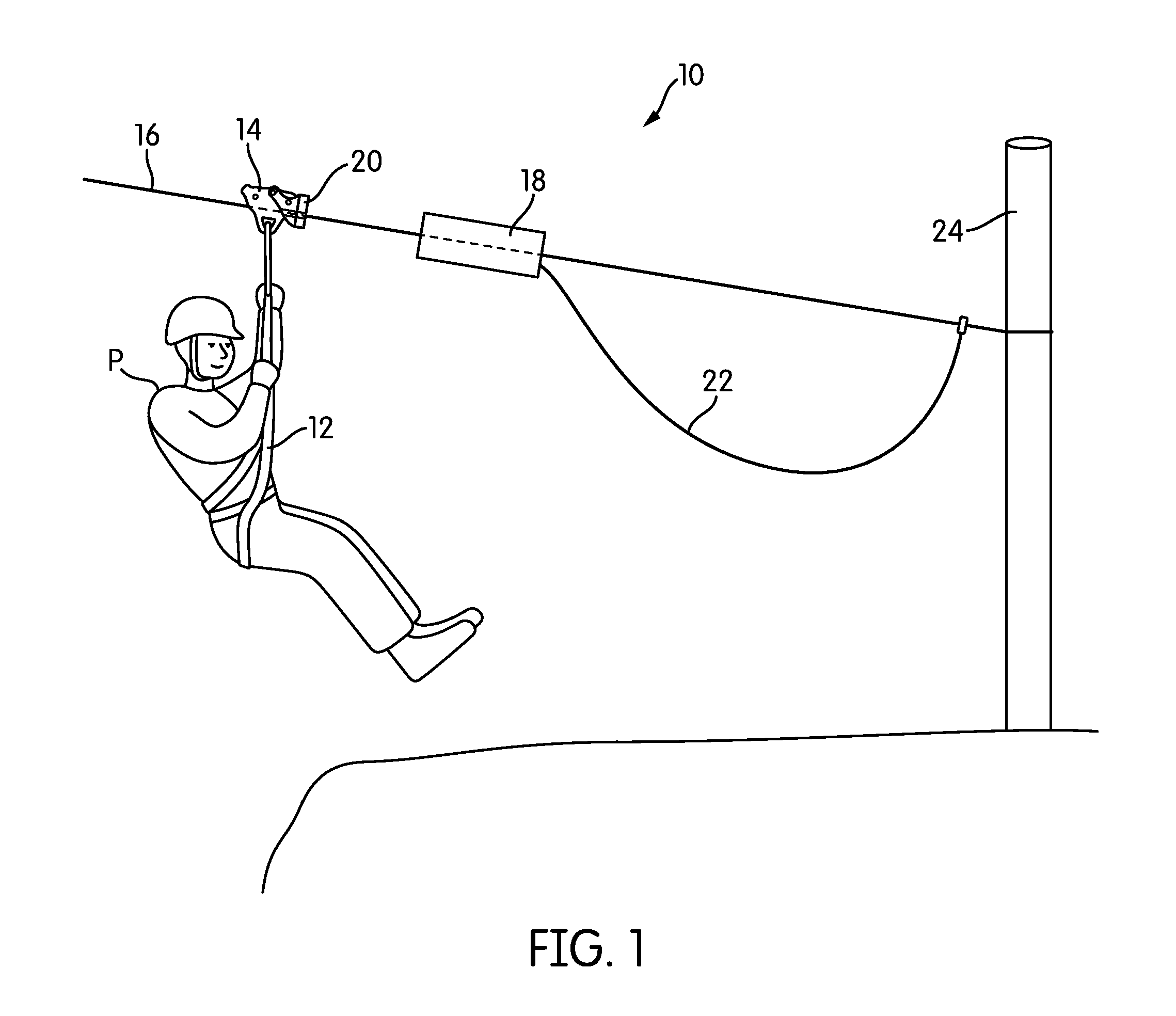
[0028]FIG. 1 is a perspective view of a capture and braking system according to an embodiment of the invention, generally indicated at 10, in use. As shown in FIG. 1, a passenger P is attached by way of a harness 12 to a trolley 14 that rides on a zip line 16. Positioned on the zip line 16 is a brake 18. The trolley 14 includes an engaging mechanism 20 that connects to and engages with the brake 18 when the two 18, 20 come into contact with one another, as will be described below in more detail.

[0029]As shown in FIG. 1, the brake 18 is connected by a rope or line 22 either to the zip line 16 itself or to a zip line support 24 at the end of the zip line 16. The arrangement of the brake 18 and the line 22 is such that the brake 18 can be thrown or slid out along the zip line 16 some distance away from the support 24, so that the trolley 14 will contact the brake 18 some distance before the end of the zip line 16, giving the brake 18 time and space to slow and stop the trolley 14 and t...


PUM


Abstract

A brake and capture system for zip lining are disclosed. The brake has a housing with first and second ends. Inside the brake are a number of fixed guide plates, each with an angled slot. A number of wheels are mounted are movably mounted within the housing so as to be guided by the angled slots. When the brake is struck by a trolley with sufficient momentum, the wheels within the brake are driven inwardly by the angled slots, into rolling engagement with the zip line, to slow the trolley. The trolley and brake may be provided with complementary engaging structures, such that the brake may be sent out on the zip line to capture the trolley if it has insufficient momentum.

Description

CROSS-REFERENCE TO RELATED APPLICATIONS[0001]This application claims priority to U.S. Provisional Patent Application No. 61 / 735,480, filed Dec. 10, 2012. The contents of that application are incorporated by reference in their entirety.BACKGROUND OF THE INVENTION[0002]1. Field of the Invention[0003]In general, the invention relates to equipment and apparatuses for zip lining, and more particularly to a brake and capture system for zip lining.[0004]2. Description of Related Art[0005]A zip line is a rope line or wire suspended above the ground, typically on an incline. Zip lines are usually suspended at least several meters above the ground, and heights of over 100 meters have been used. In zip lining, a trolley or pulley system is mounted on the zip line, and a passenger travels from one end of the zip line to the other, propelled by gravity, by hanging from the trolley. Zip lines themselves are not new; however, zip lining has recently been growing in popularity as a recreational act...

Claims


Application Information

Patent Timeline
IPC IPC(8): B61H9/02
CPCB61H9/02F16D63/008
Inventor HACKETT, DONALD
Owner HACKETT DONALD
Why Eureka
Try Eureka